 Kanger Glass-ceramic Co., Ltd.
Appliance control panel glass mounting clearance design defines how a touch or display glass panel fits its bezel, housing, adhesive or gasket, sensor layer, and supporting electronics. The relevant gap is the panel-to-housing interface, not the working space in front of an electrical distribution panel or the cabinet installation gap around an appliance. The released drawing should identify the datums, assembly state, temperature condition, and measurement method for each critical edge.
This drawing-led guide for appliance control panel glass mounting clearance design is intended for appliance OEM, industrial-design, supplier-quality, and glass-engineering teams. It does not set a universal dimension, print specification, material approval, test limit, or product guarantee. Use the released panel drawing, supplier data for the exact glass and process, applicable appliance requirements, and validation on production-intent control modules.
Separate the glass interface from other clearances
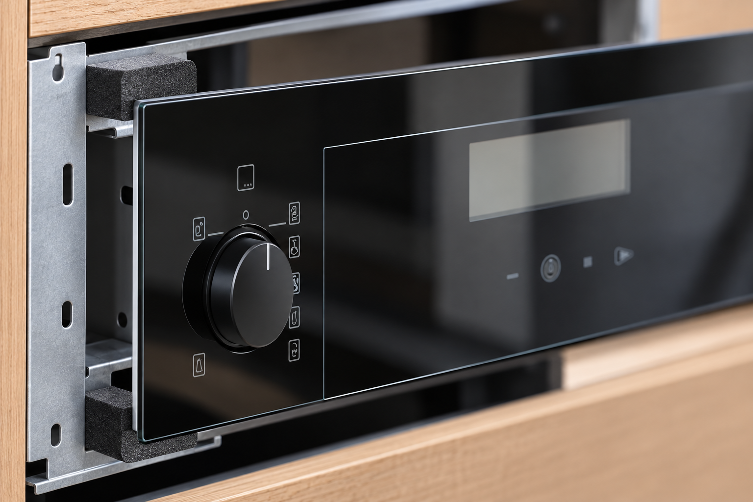
Name the surfaces first: glass edge to bezel, glass rear face to sensor or display stack, bezel to housing, and housing to the appliance chassis. These dimensions have different functions and owners. A front-control overlay also differs from a passive inspection window because touch regions, display apertures, and printed symbols must remain aligned with electronics after assembly.
Use a section view to label the glass, housing, sensor film or electrode, display window, gasket or adhesive, and nearby PCB. Identify which dimensions the glass supplier controls and which are set by the appliance assembler. Avoid using cabinet ventilation or electrical service spacing as a glass acceptance criterion.
Establish datums and check locations
Choose a primary datum on the appliance housing or bezel that can be reproduced in production. Mark the locations where the panel-to-bezel gap, display opening, control icon position, and panel flushness will be measured. A single nominal dimension can miss local bezel bow, corner tightness, or an offset caused by a misplaced carrier.
Define whether measurements are taken on the loose panel, in the assembled control module, or after the module is installed in the appliance. Name the fixture, supported surfaces, orientation, and instrument. If a dimension is checked optically, state the reference edge or fiducial used to avoid measuring from a printed boundary that can vary.
Build the tolerance stack across layers
Include glass width and height, corner geometry, bezel opening, coating or print boundary, adhesive or gasket thickness, sensor-layer position, PCB support, and housing variation. Consider the minimum edge clearance and the maximum unsupported span separately. If a touch electrode or optical display is referenced to the panel, include its position tolerance in the same stack.
Identify each input, source drawing, process owner, and revision. Do not combine worst-case tolerances from unrelated datums without checking the actual assembly chain. When measurement uncertainty is material near a limit, document the method and repeatability; NIST TN 1297 provides general guidance for expressing measurement uncertainty, not appliance glass tolerances.
Account for temperature and surrounding components
A control panel on an oven, hood, dishwasher, or range can experience different temperature and humidity profiles depending on its location, ventilation, duty cycle, and nearby electronics. A panel above a cavity or near a motor is not exposed like a remote wall control. Do not use a single appliance set point as the glass surface temperature.
Set thermal inputs from the product design or measurement plan and validate the assembled construction. Include the glass type, coating, print, adhesive, gasket, carrier, and electronics in the test specimen where they affect movement. IEC 60335-2-6 defines appliance-level safety scope for stationary household cooking appliances; its public description does not provide a universal panel clearance value.
Protect touch response and display alignment
The rear stack can determine capacitive touch sensitivity, display readability, light leakage, and button alignment. A gap change may alter electrode spacing or create a visible offset even when the glass edge remains free. Define functional zones and keep the mechanical tolerance stack linked to the relevant sensor or display drawings.
Check operation across the intended touch locations and viewing angles after assembly and environmental exposure. Record false activations, missed inputs, display clipping, light bleed, or visible bezel misalignment using the appliance’s own acceptance criteria. Do not infer electrical performance from a mechanical gap measurement alone.
Design edge support and retention
State whether the glass is captured, bonded, gasketed, or supported by a combination. Specify contact pads, fastener locations, adhesive lands, assembly sequence, and any required compliant layer. Avoid point loading an edge or forcing a panel flat against a distorted bezel. Corners and openings near display or control regions can be more sensitive than a straight edge.
Inspect the panel for edge damage, scratches, coating lift, and print contact after assembly. Ensure tools and fixtures do not load the active touch surface. If rework is allowed, state how the panel is removed, cleaned, and reinstalled without damaging the sensor stack or changing the spacing.
Measure with a repeatable method
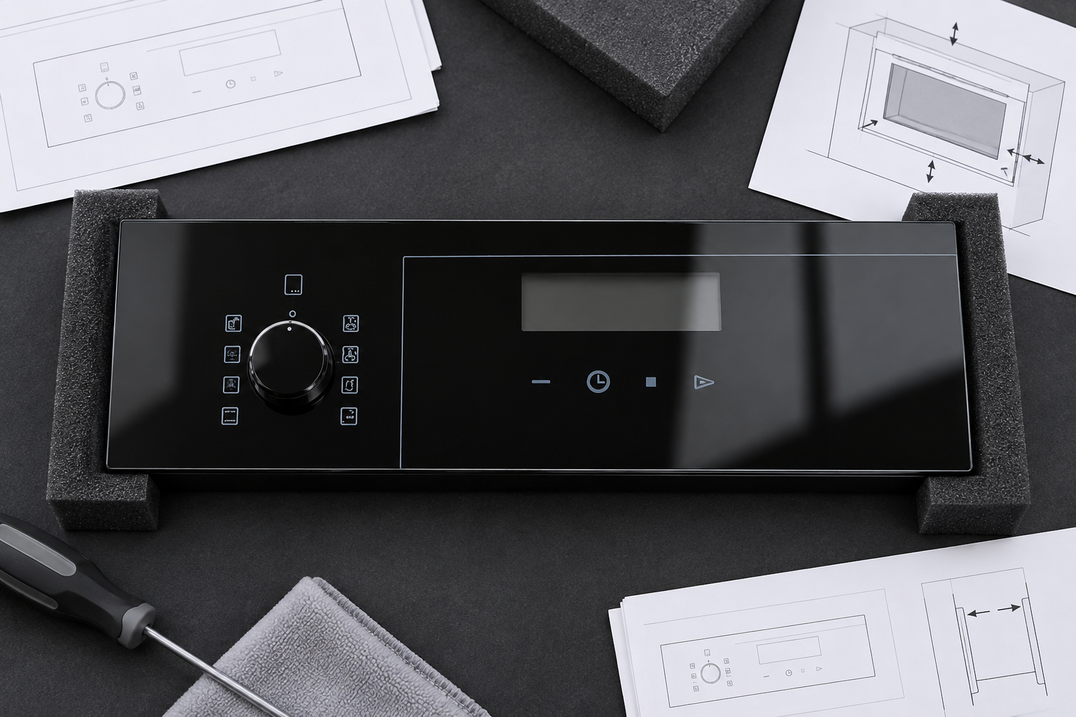
Use a defined method for each feature: a fixture and feeler gauge for accessible perimeter gaps, optical measurement for display-to-artwork registration, or a probe for flushness where contact will not damage the surface. Specify instrument resolution, calibration, contact force, sample identity, and the number of edge points.
Compare measurement repeatability with the tolerance before treating a marginal result as a pass or fail. Keep the raw observations and fixture setup with the lot record. NIST TN 1297 explains how measurement results and uncertainty can be documented; apply an appropriate method for the actual measurand and process.
Validate the complete control module
Build production-intent modules with the released glass, bezel, sensor, PCB, gasket or adhesive, and fasteners. Test the expected heat, humidity, cleaning, vibration, and operating cycles for the actual appliance environment. Confirm both mechanical fit and user-interface function after exposure.
Capture pre- and post-test gap readings, alignment images, touch-response results, display checks, sample lot, equipment, and disposition. A room-temperature fit check does not demonstrate that the panel remains aligned after the specified duty. Repeat validation when glass, coating, print, adhesive, housing, electronics, fixture, supplier, or thermal location changes.
Engineering table
| Feature | Definition to release | Verification record |
|---|---|---|
| Edge gap | Datum, points, and assembly state | Fixture method and measurements |
| Display alignment | Glass datum to display aperture | Overlay image or optical readings |
| Touch stack | Glass, sensor, adhesive, and carrier order | Functional response after assembly |
| Thermal allowance | Defined product location and exposure | Pre/post-cycle fit and function |
| Change control | Glass, bezel, sensor, process, and supplier revisions | Review and revalidation decision |
RFQ, first-article, and production workflow
For an RFQ, provide the controlled panel drawing, appliance function and location, glass type and thickness, edge and corner details, artwork and layer files, sensor or display stack, gasket or adhesive interface, volumes, packaging, and required validation conditions. Ask suppliers to identify process assumptions and deviations in writing. Make each quotation and inspection plan refer to the same revision.
Before first-article approval, verify glass identity, dimensions, edge condition, surface orientation, print revision, display window, touch zone alignment, seal or bezel fit, and packaging. Assemble production-intent electronics, backlight, sensor, gasket, and housing when those parts influence the result. Capture lot identity, setup, visual evidence, measurements, functional checks, and disposition.
For serial production, use named inspection methods with defined lighting, fixture, instrument, sample locations, and reaction rules. Trend results by glass and ink lot, screen or cure setup, supplier, and assembly line. If a defect appears, contain related inventory, preserve failed samples before rework, compare the affected lot with the approved master, and verify correction on a later production run.
Educational video: engineering drawings
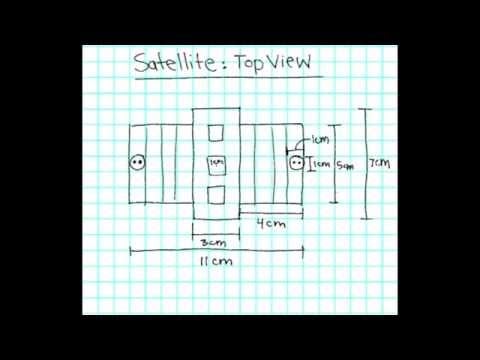
This NASA BEST Students introduction explains how a drawing communicates component geometry. Use it as background for recording the panel outline, edge interfaces and mating-part locations; it does not establish a glass clearance or sealing limit.
Related Kanger resources
- Tempered glass for household appliances and controllers
- Inspection Windows Glass for Appliances: OEM Specification Guide
- How should OEMs specify inspection windows glass for appliances?
- Designing the Sealing Interface Around Appliance Control Panel Glass
For an application review, provide the released panel drawing, appliance location, touch or display requirements, glass finish and artwork, assembly interface, and lot requirements. The Kanger appliance inspection-window guide gives a broader RFQ checklist; this article addresses the specific control-panel interface named above.
Frequently asked questions
Is glass mounting clearance the same as electrical-panel working space?
No. This guide concerns the glass-to-bezel or glass-to-housing fit in an appliance control module.
Can one gap value work for all control panels?
No. Glass, bezel, adhesive, sensor stack, housing, and operating environment determine the design.
Should touch response be checked after thermal exposure?
Yes, when heat or humidity can affect the glass, adhesive, sensor position, or electronics stack.
What changes require another fit review?
Glass dimensions, coatings, artwork, adhesive, bezel, sensor, PCB support, assembly process, or appliance location should be reviewed.


