 Kanger Glass-ceramic Co., Ltd.
Appliance control panel glass sealing interface design must define how the glass perimeter, bezel, gasket or adhesive, and electronics enclosure work together to limit unwanted ingress while preserving touch and display functions. This interface is not automatically the appliance door seal or a hermetic glass-to-metal joint. The OEM should state the protected boundary, expected exposure, service needs, assembly method, and validation conditions on the released design.
This drawing-led guide for appliance control panel glass sealing interface design is intended for appliance OEM, industrial-design, supplier-quality, and glass-engineering teams. It does not set a universal dimension, print specification, material approval, test limit, or product guarantee. Use the released panel drawing, supplier data for the exact glass and process, applicable appliance requirements, and validation on production-intent control modules.
Map the protected boundary
Trace likely liquid and contamination paths across the front glass, bezel seam, button or knob openings, display window, cable entry, enclosure joints, vents, and mounting points. Separate the front-panel perimeter barrier from any internal seals protecting the PCB or the appliance chamber. A seal around glass should not be assigned functions that belong to another enclosure joint.
Draw the boundary on an assembled cross-section and identify which components create each barrier. State whether the front panel must resist spills, wiping, steam, grease, detergent, or other named exposure. Avoid assigning an IP rating unless the full product is specified and evaluated to the relevant test method.
Choose a seal architecture
A dry gasket, pressure-sensitive adhesive, dispensed adhesive, or combined stack may be appropriate depending on serviceability, retention, expected motion, and the appliance design. The choice depends on glass face, coating, print, bezel material, cleaning exposure, and process capability. A generic “waterproof seal” label does not define joint performance or compatibility.
For each proposed material, obtain supplier data for temperature, cleaning agents, aging, compression set or cure, storage, substrate preparation, and movement. Confirm that the selected material is approved for the actual glass and finish. Do not assume an adhesive suitable for a metal bezel will bond to a printed or coated glass face.
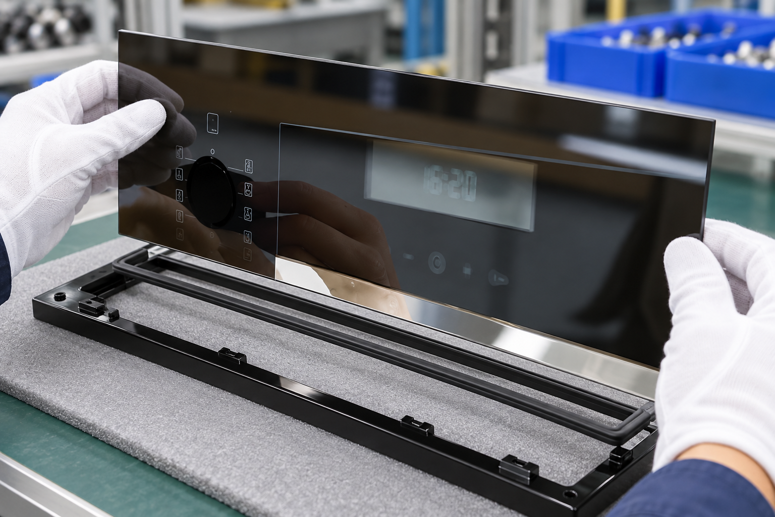
Specify joint geometry and compression
Define the seal land, contact width, edge distance, gasket section, gap, compression stops, corner route, and any bead start or stop. Include tolerances for glass size, bezel opening, panel position, flatness, and gasket placement. The worst-case stack should show whether contact is maintained without excessive pressure on the glass.
Use datum-based assembly dimensions and identify where the seal is inspected. Check local regions around corners, display cutouts, controls, and cable exits. Consider drainage or a secondary barrier when the design allows liquid to travel behind the outer panel; do not leave ingress paths implicit in a rendering.
Protect printed and coated surfaces
Identify the glass face that meets the gasket or adhesive and state whether printed borders, icons, conductive layers, or coatings may lie beneath the contact zone. Ink and coating chemistry can change adhesion or friction. Oils, dust, release residue, and cleaner left on the bonding surface can reduce repeatability.
Define handling gloves, cleaning agent, lint control, surface inspection, and preparation-to-assembly time when relevant. Require the panel orientation to be marked or controlled so the specified surface is assembled inward or outward correctly. Inspect squeeze-out and keep the viewing and touch zones free of adhesive or gasket intrusion.
Design corners and transitions
Corners combine a radius mismatch, compressed gasket, splice or bead start, local bezel stiffness, and glass edge support. Straight sections cannot prove continuity at a corner. Specify whether the gasket is continuous, molded, spliced, or dispensed and define acceptable joint placement relative to controls, display openings, and high-exposure areas.
Validate production-intent corners and transitions. Check for gaps, wrinkles, lifted material, excess adhesive, trapped contamination, edge contact, and obstruction of controls. If the panel uses a shaped or cutout geometry, measure the interface around each feature rather than extrapolating from one edge.
Control assembly and service
Document placement fixture, centering, compression stops, clip or fastener sequence, adhesive cure, environmental limits, and rework rules. A seal’s final compression depends on the actual stack and installation process, not just the nominal gasket size. Make in-process checks measurable and keep pressure off unsupported glass edges.
If the panel is serviceable, define how a gasket or adhesive is removed and replaced without scratching the glass, damaging the print, or leaving residue. Record material lot, expiry, surface prep, dispense setup, operator, and inspection. Rework should restore the approved interface rather than create an untracked variation.

Validate the assembled control panel
Select tests from the specified exposure: controlled splash or wipe, cleaner contact, humidity, temperature cycles, vibration, touch operation, display legibility, and aging where appropriate. Define orientation, fluid, dwell, conditioning, sequence, sample configuration, and acceptance before testing. The chosen exposure must represent the appliance environment instead of a convenient generic test.
Inspect the enclosure and electronics for ingress, corrosion, residue, seal movement, glass shift, print damage, touch faults, and display issues. Run the test on production-intent modules at tolerance extremes when they affect contact. The appliance-level requirements in IEC 60335-2-6 provide safety context for household cooking appliances; the particular panel interface still needs product-specific qualification. Preserve baseline and post-exposure photos at fixed viewing angles. Tie every result to the software or touch-sensor revision, because an apparent control fault can arise from a configuration change rather than from glass fit or sealing.
Release inspection and change controls
The drawing, material list, process instruction, and inspection plan should identify the seal function, approved materials, glass surface, geometry, method, sampling, acceptance, and reaction owner. Link first-article photos and validation records to the panel and housing revisions. Ensure supplier replies and purchase documents reference the same controlled package.
Review changes to glass type, thickness, coating, print, bezel, gasket, adhesive, primer, cleaner, sensor stack, fixture, cure, supplier, packaging, or exposure. A change to artwork or coating may affect a bond line even when the outside glass dimensions are unchanged. Record whether fit analysis, compatibility review, or revalidation is required.
Engineering table
| Seal control | Drawing or process requirement | Evidence |
|---|---|---|
| Boundary | Protected enclosure and exposure path | Section view and risk map |
| Geometry | Land, gap, compression, and corner path | Tolerance stack and measurements |
| Material | Approved gasket/adhesive and glass face | Supplier compatibility data |
| Assembly | Placement, stops, cure, and service steps | First-article process record |
| Qualification | Exposure and functional sequence | Ingress, visual, touch, and display results |
RFQ, first-article, and production workflow
For an RFQ, provide the controlled panel drawing, appliance function and location, glass type and thickness, edge and corner details, artwork and layer files, sensor or display stack, gasket or adhesive interface, volumes, packaging, and required validation conditions. Ask suppliers to identify process assumptions and deviations in writing. Make each quotation and inspection plan refer to the same revision.
Before first-article approval, verify glass identity, dimensions, edge condition, surface orientation, print revision, display window, touch zone alignment, seal or bezel fit, and packaging. Assemble production-intent electronics, backlight, sensor, gasket, and housing when those parts influence the result. Capture lot identity, setup, visual evidence, measurements, functional checks, and disposition.
For serial production, use named inspection methods with defined lighting, fixture, instrument, sample locations, and reaction rules. Trend results by glass and ink lot, screen or cure setup, supplier, and assembly line. If a defect appears, contain related inventory, preserve failed samples before rework, compare the affected lot with the approved master, and verify correction on a later production run.
Educational video
This neutral Corning Museum of Glass video provides background on glass coloration and surface appearance. It is additional learning material only; it does not qualify an appliance control panel or replace a product-specific test.

Related Kanger resources
- Tempered glass for household appliances and controllers
- Inspection Windows Glass for Appliances: OEM Specification Guide
- How should OEMs specify inspection windows glass for appliances?
- How to Set Mounting Clearances for Appliance Control Panel Glass Under Thermal Expansion
For an application review, provide the released panel drawing, appliance location, touch or display requirements, glass finish and artwork, assembly interface, and lot requirements. The Kanger appliance inspection-window guide gives a broader RFQ checklist; this article addresses the specific control-panel interface named above.
Frequently asked questions
Does the panel gasket seal the entire appliance?
Not automatically. The glass perimeter, internal electronics enclosure, and appliance chamber may be separate boundaries.
Can the same adhesive be used with any printed glass?
No. Confirm compatibility with the exact print, coating, glass surface, cleaning process, and service temperature.
Why are corners inspected separately?
They combine radius variation, joints, local compression, and frame stiffness changes.
When should the seal interface be revalidated?
When the glass, finish, bezel, gasket, adhesive, process, cleaner, or operating exposure changes.


