 Kanger Glass-ceramic Co., Ltd.
Glass ceramic cooktop panel mounting clearance design must let the panel, frame, gasket, adhesive, and nearby components move without creating hard contact or concentrated edge load. The correct gap is not a universal number. It depends on panel dimensions, material data, frame expansion, temperature distribution, support scheme, manufacturing tolerances, assembly offset, and the maximum credible thermal cycle. Engineers should calculate relative movement in each direction, add tolerance stack-up and installation allowance, then validate the complete appliance through dimensional checks and representative hot-cold cycling. The released drawing should define the datum, nominal position, minimum residual clearance, supports, seal compression, and inspection method.
This guide turns the search intent behind glass ceramic cooktop panel mounting clearance design into a drawing-led OEM workflow. It does not supply a universal dimension or material approval; the released appliance design, applicable standards, verified supplier data, and representative validation remain controlling.
Start with the complete assembly stack
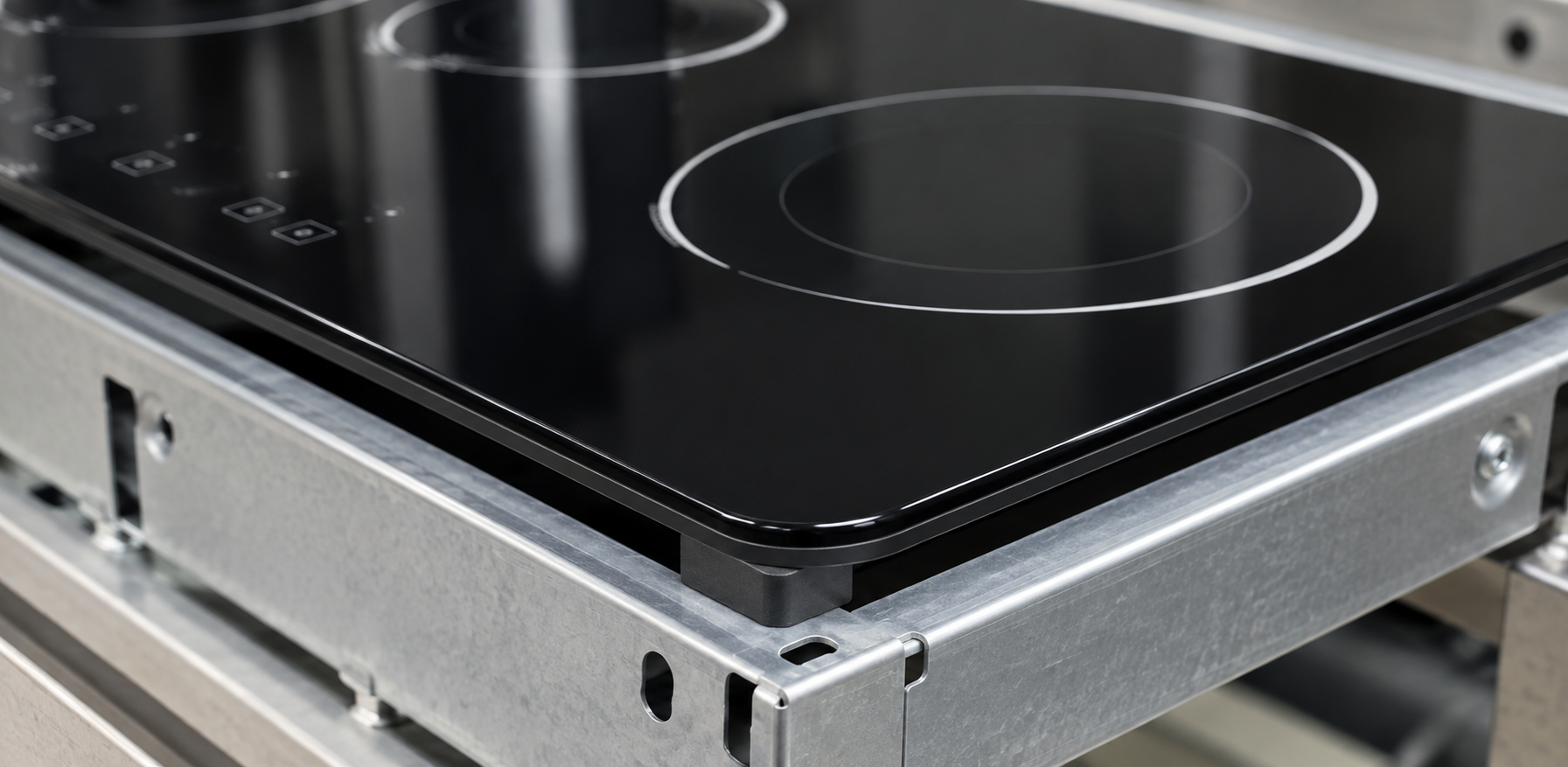
Map every component that can influence the panel position: glass-ceramic, metal frame, support blocks, gasket, adhesive, heater carrier, trim, fasteners, and control modules. Identify where the panel is intentionally supported and where it must remain free. A clearance that looks generous in a CAD screenshot can disappear when a frame bows, adhesive thickness varies, or the panel is installed off center. Mark all possible hard-contact paths, especially corners, cutouts, and metal features close to finished edges.
For this glass ceramic cooktop panel mounting clearance design decision, record the owner, input source, drawing field, verification method, and reaction to missing evidence. Review the requirement with appliance engineering, quality, manufacturing, purchasing, and the glass supplier so that each team works from the same datums, conditions, and acceptance language. Where risk is high, test tolerance extremes instead of relying only on a nominal sample.
Define temperatures and movement directions
Use the temperatures of the actual parts, not only the user-selected cooking level. The glass surface, underside, frame, supports, and trim can reach different temperatures and can heat at different rates. Define the assembly temperature, normal steady conditions, local hot zones, cooldown, and credible upset conditions. Evaluate movement along length and width as well as vertical lift, bow, and frame distortion. Low-expansion glass-ceramic still sits inside an assembly whose other materials may move appreciably.
For this glass ceramic cooktop panel mounting clearance design decision, record the owner, input source, drawing field, verification method, and reaction to missing evidence. Review the requirement with appliance engineering, quality, manufacturing, purchasing, and the glass supplier so that each team works from the same datums, conditions, and acceptance language. Where risk is high, test tolerance extremes instead of relying only on a nominal sample.
Calculate relative movement without false precision
A first estimate multiplies original length by the difference in thermal expansion and the temperature change. Apply it independently to the panel and mating frame, then compare their movement from the chosen locating datum. Use verified material data across the relevant temperature range; do not substitute a marketing label for engineering values. The calculation is a screening model because temperature is rarely uniform and joints, bends, and fasteners change how a frame responds. Keep inputs and assumptions visible for review.
For this glass ceramic cooktop panel mounting clearance design decision, record the owner, input source, drawing field, verification method, and reaction to missing evidence. Review the requirement with appliance engineering, quality, manufacturing, purchasing, and the glass supplier so that each team works from the same datums, conditions, and acceptance language. Where risk is high, test tolerance extremes instead of relying only on a nominal sample.
Add manufacturing and assembly tolerance
Thermal movement is only one part of the minimum gap. Stack panel size, frame opening, corner radius, support position, gasket variation, adhesive bead, fixture repeatability, and installation offset using the organization’s approved tolerance method. Consider worst credible lateral shift rather than assuming the panel remains centered. If the design uses one fixed locating edge and floating supports elsewhere, state that explicitly. The drawing should distinguish nominal cosmetic gap from the residual clearance required for safety and durability.
For this glass ceramic cooktop panel mounting clearance design decision, record the owner, input source, drawing field, verification method, and reaction to missing evidence. Review the requirement with appliance engineering, quality, manufacturing, purchasing, and the glass supplier so that each team works from the same datums, conditions, and acceptance language. Where risk is high, test tolerance extremes instead of relying only on a nominal sample.
Design supports and restraints together
Supports should distribute load, protect edges, and allow intended movement. Avoid rigid point contact on corners or cutout edges. Retaining clips and trim must not clamp the panel so tightly that thermal expansion becomes stress. Gaskets can locate and cushion the part, but their compression range, recovery, aging, and temperature exposure need qualification. Adhesive systems require controlled bond-line thickness and a movement capability consistent with the joint geometry and cure process.
For this glass ceramic cooktop panel mounting clearance design decision, record the owner, input source, drawing field, verification method, and reaction to missing evidence. Review the requirement with appliance engineering, quality, manufacturing, purchasing, and the glass supplier so that each team works from the same datums, conditions, and acceptance language. Where risk is high, test tolerance extremes instead of relying only on a nominal sample.
Control edge and corner interfaces
Finished edges are vulnerable to chips and contact damage. Keep metal burrs, welds, screw heads, and hard contamination outside the movement envelope. Rounded frame corners must accommodate the panel radius plus positional tolerance; a nominally larger opening can still touch near a mismatched corner. Check cutouts and control-window features for nearby brackets or harnesses. Protective film, temporary shims, and assembly tools must be removed or controlled so they do not become unintended contacts.
For this glass ceramic cooktop panel mounting clearance design decision, record the owner, input source, drawing field, verification method, and reaction to missing evidence. Review the requirement with appliance engineering, quality, manufacturing, purchasing, and the glass supplier so that each team works from the same datums, conditions, and acceptance language. Where risk is high, test tolerance extremes instead of relying only on a nominal sample.
Validate with cold and hot measurements
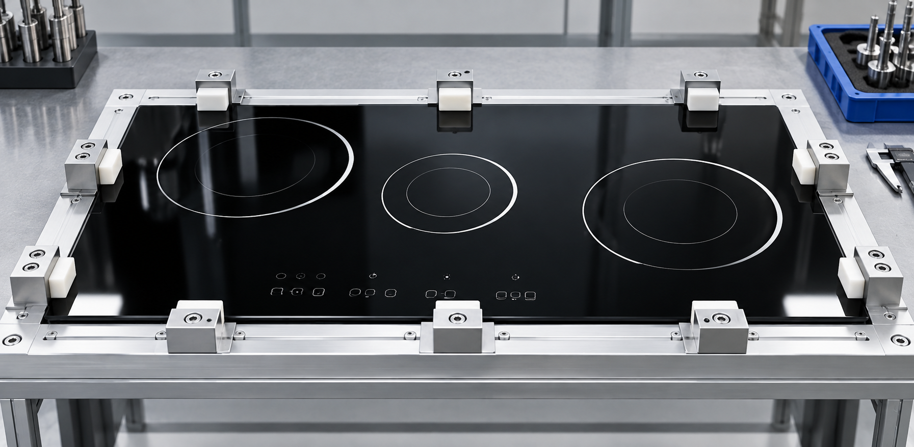
Measure the panel position at assembly temperature, through representative heating, and after cooldown. Use non-contact methods where physical probes would disturb or damage the hot assembly. Record temperatures at relevant components and correlate them with gap or displacement observations. Run samples at tolerance extremes when practical, not only nominal parts. Inspect edges, supports, gasket compression, adhesive, and frame witness marks after cycling. A passed electrical or heating test does not alone prove the mechanical clearance is adequate.
For this glass ceramic cooktop panel mounting clearance design decision, record the owner, input source, drawing field, verification method, and reaction to missing evidence. Review the requirement with appliance engineering, quality, manufacturing, purchasing, and the glass supplier so that each team works from the same datums, conditions, and acceptance language. Where risk is high, test tolerance extremes instead of relying only on a nominal sample.
Release a measurable drawing and control plan
Show datums, locating features, nominal gaps, minimum residual clearance, support locations, allowable contact zones, gasket or adhesive requirements, and measurement points. State the inspection condition and whether the dimension is checked before or after assembly. Link the drawing to the thermal validation report and approved materials. In production, verify characteristics that actually control the clearance and track trends by lot, tool, frame supplier, and assembly station. Reassess the design when materials, panel size, frame geometry, heater power, or mounting process changes.
For this glass ceramic cooktop panel mounting clearance design decision, record the owner, input source, drawing field, verification method, and reaction to missing evidence. Review the requirement with appliance engineering, quality, manufacturing, purchasing, and the glass supplier so that each team works from the same datums, conditions, and acceptance language. Where risk is high, test tolerance extremes instead of relying only on a nominal sample.
Engineering table
| Design input | Record | Why it controls clearance |
|---|---|---|
| Panel and frame geometry | Dimensions, datums, corner radii, cutouts | Defines nominal space and possible contact paths |
| Thermal duty | Assembly, local peak, steady and cooldown temperatures | Determines relative movement and distortion |
| Materials | Verified expansion data over the relevant range | Supports movement calculation |
| Tolerance stack | Part, fixture and assembly variation | Protects the minimum residual gap |
| Supports and seals | Location, compression, hardness and aging condition | Controls position, load and movement |
Supplier RFQ and first-article checklist
Send the supplier the controlled drawing and CAD data, material requirement, panel size, edge and decoration details, annual demand, lot pattern, packaging requirement, and appliance-level validation conditions. Ask the supplier to identify feasibility limits and deviations in writing. Commercial quotations should reference the same drawing revision that quality and production will use.
Before approving a first article, check document identity, dimensions, edge quality, surface orientation, printed features, and the specific interface covered by this guide. Assemble the sample with production-intent frame, seals, supports, and retention. Record photographs, measurements, temperatures where relevant, equipment identity, and the exact sample lot. Preserve approved masters and rejected evidence.
For serial production, inspect the characteristics that control function rather than adding unrelated measurements. Trend results by lot, tool, material batch, supplier, and assembly station. When nonconformity appears, contain affected stock, preserve samples before rework, compare with the approved setup, and verify corrective action on subsequent lots. Requalification should follow material, geometry, process, tooling, or supplier changes according to documented risk.
Educational video
This neutral educational video from Corning Museum of Glass provides useful background on glass processing and stress. It does not replace engineering calculations, appliance instructions, or qualification.

Related Kanger resources
- Black glass-ceramic product page
- Glass-ceramic material overview
- White ceramic glass thermal shock test
- White ceramic glass sealing interface design
For a drawing-led quotation, send Kanger the application, controlled files, expected quantities, and validation requirements. Technical review can identify missing interface information without turning this general guidance into an unsupported product guarantee.
Frequently asked questions
Is there one standard mounting gap for every cooktop panel?
No. The required clearance depends on geometry, materials, thermal field, supports, tolerances, assembly offset, and the validated appliance design.
Should low-expansion glass-ceramic be installed with zero clearance?
No. The frame, gasket, adhesive, and other parts move, and manufacturing variation can create contact even when panel expansion is small.
Where should the panel be located in the frame?
Use drawing-defined datums and controlled supports. Some designs fix one reference and allow movement elsewhere, but the strategy must be validated.
How is mounting clearance verified?
Check defined gaps and support conditions cold, observe movement during representative thermal cycles, inspect after cooldown, and record temperatures and tolerance conditions.


