 Kanger Glass-ceramic Co., Ltd.
Infrared cooker glass corner radius specification should connect the visible corner shape to the mating frame, edge finish, manufacturing route, measurement method, and appliance-level validation. A radius callout by itself does not define corner profile, transition, tolerance, edge condition, or the clearance needed through assembly and thermal movement. The OEM drawing must make the requirement measurable and functionally justified while avoiding unsupported universal minimums.
This guide turns the intent behind infrared cooker glass corner radius specification into a drawing-led OEM workflow. It does not invent a universal limit, material property, certification, or guarantee. Released requirements, supplier evidence, applicable standards, and representative appliance validation remain controlling.
For an infrared cooker, check each radius against the radiant-element layout, metal frame, reflector, seal path, controls, and the illuminated cooking-zone artwork. The edge geometry must be manufacturable and must fit the production frame without forcing the panel or concentrating load near a hot zone.
Define the corner function first
List whether the corner is exposed, framed, bonded, sealed, clipped, or hidden. Consider appearance, handling, packaging, frame clearance, gasket path, adhesive geometry, cleaning, and local stress. The same nominal radius can behave differently when the edge is polished, beveled, printed, coated, or positioned close to a metal corner. Write the functional reason beside the engineering decision.
For this decision, record the responsible owner, input source, method, acceptance evidence, and reaction to missing information. Review it with design, quality, manufacturing, purchasing, service, and the glass supplier. Use production-intent parts and tolerance extremes when nominal samples cannot resolve the risk, and keep every result linked to the controlled lot and revision.
Specify the complete corner geometry
Define the plan-view radius, tolerance, transition to straight edges, symmetry, tangent requirement, and any chamfer, bevel, or edge radius. Identify which CAD or drawing view controls if the files disagree. For non-circular or blended corners, use profile control or coordinates rather than forcing an inaccurate single-radius note. State units and avoid ambiguous phrases such as typical or smooth unless backed by a controlled master.
For this decision, record the responsible owner, input source, method, acceptance evidence, and reaction to missing information. Review it with design, quality, manufacturing, purchasing, service, and the glass supplier. Use production-intent parts and tolerance extremes when nominal samples cannot resolve the risk, and keep every result linked to the controlled lot and revision.
Coordinate the mating frame and gap
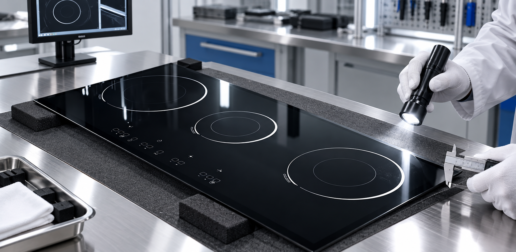
Compare panel and frame radii over the complete tolerance stack. Include frame opening size, weld or formed-corner variation, assembly position, gasket, adhesive, and thermal movement. A larger panel radius does not automatically guarantee clearance if the center is shifted or a metal feature protrudes. Evaluate diagonal contact and define measurable gap locations for the assembled appliance.
For this decision, record the responsible owner, input source, method, acceptance evidence, and reaction to missing information. Review it with design, quality, manufacturing, purchasing, service, and the glass supplier. Use production-intent parts and tolerance extremes when nominal samples cannot resolve the risk, and keep every result linked to the controlled lot and revision.
Control edge finish through the corner
The corner process must maintain the specified edge quality through changing direction. Define allowable chips, shells, sharpness, polish or grind appearance, and transition marks using an approved inspection method. Avoid local notches or handling damage. Packaging separators and fixtures should support the panel without pressing the corners, and incoming inspection should examine all four corners under controlled light.
For this decision, record the responsible owner, input source, method, acceptance evidence, and reaction to missing information. Review it with design, quality, manufacturing, purchasing, service, and the glass supplier. Use production-intent parts and tolerance extremes when nominal samples cannot resolve the risk, and keep every result linked to the controlled lot and revision.
Select a capable manufacturing method
Discuss cutting, grinding, finishing, printing, cleaning, and handling capability with the supplier before release. Tight radii or narrow transitions may require different tools and create more variation or cost. Tool path, wheel condition, feed, support, and inspection access can affect the result. Use supplier evidence and trials rather than specifying geometry that cannot be measured or consistently produced.
For this decision, record the responsible owner, input source, method, acceptance evidence, and reaction to missing information. Review it with design, quality, manufacturing, purchasing, service, and the glass supplier. Use production-intent parts and tolerance extremes when nominal samples cannot resolve the risk, and keep every result linked to the controlled lot and revision.
Choose a repeatable measurement method
A radius gauge may screen accessible corners but depends on contact and visual interpretation. Optical comparators, vision systems, templates, or coordinate measurements can provide richer profile data when alignment and software settings are controlled. Define datum, inspected surface, point density, filtering, temperature, and calculation. Ensure measurement uncertainty is small enough for the tolerance decision.
For this decision, record the responsible owner, input source, method, acceptance evidence, and reaction to missing information. Review it with design, quality, manufacturing, purchasing, service, and the glass supplier. Use production-intent parts and tolerance extremes when nominal samples cannot resolve the risk, and keep every result linked to the controlled lot and revision.
Validate first articles in the appliance
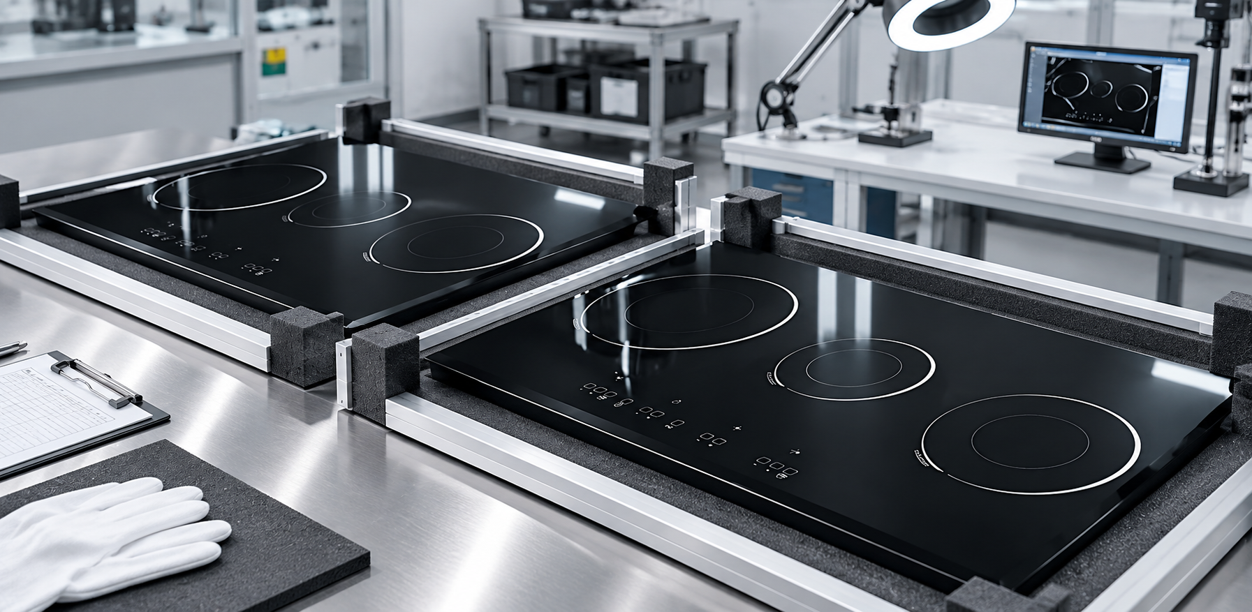
Record panel lot, drawing, CAD, edge specification, frame revision, measurement results, and photographs. Assemble production-intent samples at positional and dimensional extremes. Check perimeter and diagonal clearance, rocking, gasket continuity, adhesive, trim, appearance, controls, heating, transport, and representative cycles. Preserve approved corner samples or images for production comparison.
For this decision, record the responsible owner, input source, method, acceptance evidence, and reaction to missing information. Review it with design, quality, manufacturing, purchasing, service, and the glass supplier. Use production-intent parts and tolerance extremes when nominal samples cannot resolve the risk, and keep every result linked to the controlled lot and revision.
Control changes and serial production
Trend corner measurements and defect findings by lot, tool, wheel, process, supplier, and frame. Contain units with chips, sharp features, or suspect contact and preserve evidence before rework. Revalidate changes to radius, panel size, edgework, material, frame, gasket, adhesive, tooling, packaging, or supplier. Keep purchase orders, inspection plans, and work instructions aligned with the released revision.
For this decision, record the responsible owner, input source, method, acceptance evidence, and reaction to missing information. Review it with design, quality, manufacturing, purchasing, service, and the glass supplier. Use production-intent parts and tolerance extremes when nominal samples cannot resolve the risk, and keep every result linked to the controlled lot and revision.
Engineering table
| Drawing field | Define | Verification |
|---|---|---|
| Plan radius | Value, tolerance and transition | Gauge or profile measurement |
| Edge finish | Bevel, polish, chips and sharpness | Controlled visual/optical method |
| Mating frame | Opening, radius and tolerance stack | Assembly gap check |
| Thermal movement | Approved data and temperature envelope | Calculation plus thermal validation |
| Records | Lot, revision, instrument and images | First-article and serial report |
RFQ, first-article, and production control
At RFQ, provide the controlled drawing and CAD or artwork, application, panel dimensions, edge and surface requirements, annual quantity, packaging, and validation conditions. Ask the supplier to identify assumptions, feasibility limits, and deviations in writing. The quotation, production traveler, and inspection instruction should reference the same released package.
Before first-article approval, verify document identity, dimensions, edge condition, surface, graphics, packaging, and the topic-specific evidence in this guide. Assemble samples in production-intent frames, supports, seals, controls, and thermal hardware when those interfaces can influence the result. Record equipment, setup, sample lot, measurements, photographs, exposure, and disposition.
For serial production, translate the release into supplier and receiving checks with named methods, equipment, sample identity, and reaction plans. Trend results by lot, tool, material batch, print screen, package position, and supplier. When nonconformity appears, contain related material, preserve original evidence before rework, compare it with the approved setup, and verify corrective action on later lots.
Educational video
This neutral Corning Museum of Glass video gives useful background on glass processing and stress. It does not replace calculations, drawings, appliance instructions, or qualification.

Related Kanger resources
- Black glass-ceramic product page
- Glass-ceramic material overview
- Infrared cooker glass corner radius requirements
- Infrared cooker glass mounting clearance design
For a drawing-led quotation, send Kanger the application, controlled files, quantities, validation requirements, and schedule. Technical review can identify missing information without converting this general guidance into an unsupported product guarantee.
Frequently asked questions
Is a radius value alone enough on the drawing?
No. Include tolerance, transition, edge finish, datums or profile definition, mating-frame relationship, and the measurement method.
Can a radius gauge approve every corner profile?
It can screen simple accessible radii, but tighter or blended profiles may need an optical or coordinate method with controlled alignment.
Why must the frame radius be reviewed with the glass radius?
Panel position, tolerance, diagonal movement, frame distortion, gasket, and thermal expansion determine actual contact risk.
When should corner geometry be revalidated?
After changes to radius, panel size, edgework, material, frame, gasket, adhesive, tooling, packaging, or supplier.


