Kanger Glass-ceramic Co., Ltd.
A glass drilling machine should be selected and qualified for the substrate, thickness, hole geometry, support, and finished edge condition required by the component. Begin with the hole drawing, including its diameter, location, datum, finish, and relationship to nearby features. Then ask the processor to propose a suitable drilling and finishing route. For conventional thermal-tempered flat glass, holes belong in the fabrication stage before tempering. A machine that can make a hole in a sample does not establish that a particular appliance panel is manufacturable or that its final hole is acceptable.
Give every hole a clear function and definition
Identify whether the hole locates a component, allows a control shaft to pass, supports a fastener, provides clearance, or serves another function. The function affects what geometry and inspection matter. A clearance opening and a controlled locating hole are different requirements. Avoid specifying a nominal diameter while leaving the position, edge condition, and surrounding interface to the supplier’s interpretation.
Reference the hole to defined datums and show its relationship to the outer profile, corners, cutouts, print, and coatings. Include the finished thickness and material. The drawing should clarify whether the size is defined at the cylindrical body, a chamfer, or another profile feature. If a hardware interface needs an entry treatment or a particular shape, show that feature instead of relying on a photograph of the assembled appliance.
Confirm substrate and treatment before choosing the route
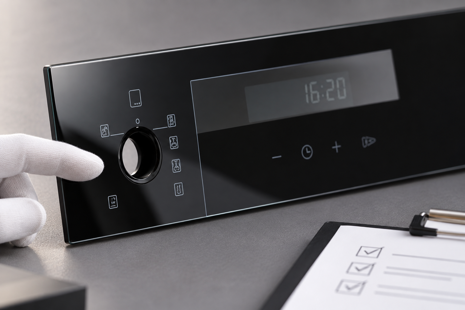
State the actual material family and current processing stage. Different glass compositions and layered products can call for different tooling and methods. A drill specification that mentions glass generally should not be treated as proof for every substrate or surface system. Request guidance from the equipment and tool suppliers and verify the proposed route on representative material.
NGA’s guidance recommends fabrication before heat treatment for conventional heat-treated flat glass. That includes drilling and related features. Do not plan to drill a delivered tempered pane as a routine field adjustment. If a hole is missing or misplaced, review the drawing, assembly requirement, and remanufacture route. A successful demonstration on an untreated scrap does not remove the boundary created by the finished pane’s treatment state.
Choose tooling as part of the machine system
Confirm tool type, mounting, permitted speed, coolant requirements where used, and application range through the actual documentation. The machine’s spindle, control, support, and access need to fit the proposed operation. A tool that mounts physically is not necessarily appropriate for the material or permitted operating conditions. Keep the approved tool identity in the setup record so replacements are controlled.
Ask the processor how the tool produces the specified finished hole and whether separate finishing is required. The rough hole and final accepted feature may have different definitions. If a tool change alters size or edge condition, the process should include a first-piece or other relevant verification. Avoid treating a catalog diameter as an independent measurement of the produced opening.
Design support for entry, exit, and part release
Review how the pane is located and supported around the feature. The method should protect the viewing face, print, and coating while allowing the intended operation. A support arrangement suitable for a small plain coupon may not represent a large control panel with nearby features. Verify that the fixture references the correct datum and does not force the pane into an unintended position.
Entry and exit conditions can differ. Inspect both faces and the hole edge, and ask how the proposed process controls breakout or other damage. Support, tool condition, operating method, and finishing can all be relevant. Use the actual equipment guidance rather than improvising a backing method on a production part. Document any sacrificial support or process aid and its replacement condition where those inputs affect the output.
Use controlled operating and coolant conditions
The approved process needs a defined operating window for the machine, tool, substrate, and hole. This guide intentionally supplies no universal spindle speed, feed, pressure, or coolant recipe. Those settings should follow equipment limits and process validation. A value copied from drilling a different material or thickness is not a qualified setting for appliance glass.
Record the settings and relevant conditions used for the first article. If the processor changes a variable during a trial, preserve the sequence and the output findings. Include tool condition and the setup state when a defect appears. A method that relies on an operator’s undocumented correction near the exit needs a clearer control or an appropriate demonstration of repeatability before it becomes the production route.
Review nearby features without inventing spacing rules
Hole-to-edge and hole-to-hole relationships can affect feasibility, treatment, assembly, and handling. The allowable geometry depends on the actual material, thickness, feature shape, process, and requirements. Do not copy one supplier’s generic minimum spacing into every drawing as a universal rule. Request a feasibility review of the actual arrangement and keep the response connected to the part revision.
If the processor proposes moving a hole or increasing a radius, review the change with the assembly designer. Check hardware alignment, gasket or adhesive contact, printed zones, and the sensor or display stack where relevant. Update the released geometry before production. A locally modified manufacturing file should not quietly become the delivered design while the OEM continues to inspect against an older drawing.
Hole specification and inspection table
| Feature or control | What the drawing or route should define | What to verify |
|---|---|---|
| Hole function | Clearance, location, shaft passage, or other intended use | Geometry supports the actual assembly interface |
| Size and profile | Diameter definition, entry treatment, and final edge form | Measured result refers to the correct feature surfaces |
| Position | Datums, coordinates, and relationship to adjacent features | Independent inspection uses the released reference system |
| Material and stage | Substrate, thickness, surface system, and treatment sequence | Trial and production represent the intended pane |
| Support and drilling | Tool, fixture, entry and exit support, and approved conditions | Both faces and the hole edge meet the agreed criteria |
| Feasibility changes | Controlled approval for any moved or revised feature | Drawing and manufacturing file remain consistent |
| Final acceptance | Dimensions, edge condition, appearance, fit, and required qualification | Finished component is checked after relevant downstream stages |
The table is a qualitative handoff. Numerical spacing, operating settings, and defect allowances must come from the actual specification and approved process.
Measure size and location with suitable methods
Choose inspection methods that resolve the hole geometry and tolerance. A plug or fit check may answer one question without establishing the complete profile or positional relationship. Optical or coordinate measurement can be useful when properly set up, but no method is automatically correct because it is more sophisticated. Define the datum, support, orientation, and feature interpretation.
NIST’s measurement-uncertainty guidance provides general context for evaluating the result. It does not select the hole tolerance or prove a particular machine’s accuracy. Preserve location-specific readings when several holes interact with an assembly. If inspectors disagree, compare the same identified sample using the same definition before deciding that the lot is nonconforming. The drawing may need clarification if the measurement boundary is ambiguous.
Qualify the finished part and the assembly interface
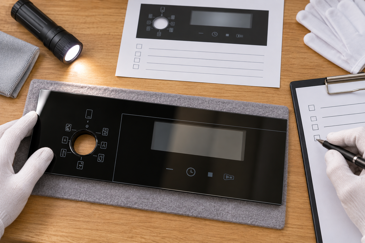
The first article should cover the relevant hole pattern, material, surface condition, and full fabrication route. Inspect the component after downstream finishing, washing, print, and treatment as applicable. Verify the intended hardware or interface using the approved assembly method. Do not force a misaligned shaft or fastener through the opening to demonstrate fit; the fixture and mating component should represent the design condition.
Document dimensional and edge results separately from functional results. A part that assembles successfully once may still have an unacceptable edge condition or poorly controlled location. Conversely, a passing dimensional report may not prove that the complete interface functions. State the scope of each check and link it to the released drawing so the evidence remains useful when the design or process changes.
Request a concrete appliance-glass quotation
Provide Kanger or the processor the drawing, substrate, treatment, hole details, surface system, mating interface, and required evidence. Ask which features are feasible and which need qualification or adjustment. Kanger’s appliance-control glass is a relevant finished-product context, but its product page does not prove a specific drilling-machine installation or guarantee every proposed hole pattern.
Capture the supplier’s confirmed requirements and agreed changes before ordering. Keep the final geometry in the controlled drawing and make replacements follow the same revision. When a later dimensional issue appears, compare drilling, downstream processing, assembly, and measurement records rather than assigning the cause from the hole’s appearance alone. The result should be a repeatable finished feature that supports the actual appliance interface.
Frequently asked questions
Can a hole be drilled after conventional glass is tempered?
Do not plan routine post-tempering drilling. Required fabrication should be resolved before heat treatment; a missing or misplaced feature may require a correctly fabricated replacement.
Is hole diameter enough for a supplier quote?
No. Include position, datums, substrate, thickness, treatment, edge form, nearby features, surface orientation, and the intended interface.
Is there one universal hole-to-edge distance?
No value in this guide should be used that way. Confirm feasibility for the actual geometry, material, process, and product requirements with the responsible supplier and engineer.
What should the inspector check on both faces?
Review entry and exit conditions, local surface damage, the hole edge, and the feature’s measured geometry. Keep those findings linked to the final-part requirements and the approved process.
Related appliance-glass resources
- Thermal Shock Resisitance Tempared Glass For Household Appliances Panel Product
- Tempered Glass Appliance Panels: OEM Specification Guide
- Can Tempered Glass Be Cut? Limits, Risks, and Safer Alternatives
- How should a cooktop-panel drawing review a glass cutout?
Sources and further reading
- NGA — fabrication before heat treatment
- NIST — measurement uncertainty
- GGF Glazing Manual — architectural-glass context, not an appliance specification
Educational video: Cutting Glass
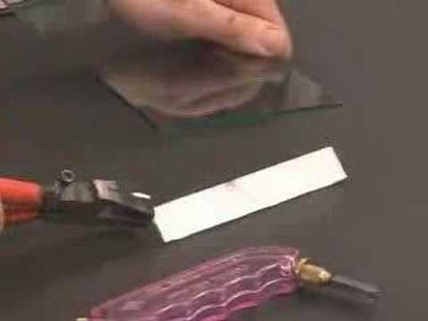
A museum demonstration of glass cutting introduces scoring and controlled separation. It is educational context, not a machine operating procedure.