Kanger Glass-ceramic Co., Ltd.
A glass edge polishing machine should be evaluated against the edge profile and quality required on the finished part. Specify the material, thickness, geometry, edge form, visible finish, dimensions, and inspection method before selecting a machine or asking a processor to quote. A shiny edge alone does not prove correct size, undamaged transitions, or suitability for an appliance assembly. For conventional tempered flat glass, required edge fabrication belongs before heat treatment. The machine is a process input; the controlled finished edge and its evidence are the useful output for an OEM buyer.
Define what polished edge means for the component
The phrase polished edge can refer to different profiles and appearance levels. Name the edge form on the drawing and show transitions at corners, holes, or cutouts where relevant. Clarify whether the edge is visible in the appliance, covered by a bezel, bonded, gasketed, or contacted by a retainer. Those interfaces can impose requirements that a simple cosmetic description misses.
Separate edge appearance from dimensions and damage criteria. A visually bright surface may still have an incorrect profile or a defect that requires attention. Conversely, an edge hidden inside an assembly may need a controlled functional finish without a decorative appearance requirement. The processor should not guess which interpretation applies. Use drawings, approved samples where appropriate, and an inspection description that the buyer and supplier can reproduce.

Match the proposed system to the geometry
Straight-line, shaped-profile, internal-feature, and other edge-processing tasks can require different equipment and tooling. Ask the processor which system is proposed for each edge and whether corners and feature transitions receive separate operations. A machine demonstration on a straight rectangle does not establish capability for an internal cutout or a small curved profile.
Identify thickness range, part size, substrate, surface system, and any access limitation. The machine’s advertised envelope is only part of feasibility. Workholding, tool access, support, handling, and the intended finish also matter. Confirm the proposed route with a representative first article. If a feature cannot be reached or finished as drawn, resolve the design change explicitly before production rather than allowing an undocumented local alteration.
Coordinate grinding and polishing stages
Polishing usually belongs to a route that establishes the edge geometry and then develops the required surface finish. The processor should define the relevant sequence, tooling, allowances, and conditions for the actual system. Do not assume a polishing stage can remove any amount of prior edge damage while preserving the finished dimension. The blank and earlier operations must supply suitable material for the approved route.
Keep rough-stage and finished-stage requirements distinct. A blank may deliberately contain an allowance that disappears during grinding. The final inspection should use the finished drawing, while intermediate checks use the process requirement. If operators compensate for an undersized blank by reducing edge finishing, the part may no longer meet the intended edge condition. Investigate the upstream cause instead of quietly changing the output definition.
Review workholding and contact protection
Locate the part with repeatable references and support it according to the proposed operation. Clamps, pads, belts, or other contact systems should not introduce unreviewed marks on viewing faces or printed areas. Inspect the support and locating surfaces as well as the finished edge. A surface scratch away from the edge may originate in handling or workholding rather than in the polishing tool.
Consider how the part enters and leaves the machine, especially when the profile contains holes or cutouts. A pane can meet the machining requirement and then acquire edge damage during transfer. Keep the handling route consistent with the approved component geometry and surface condition. The qualification should cover the relevant transitions and transfers instead of evaluating an isolated edge sample that never experiences production handling.

Use the machine’s documented operating and coolant conditions
Tooling, coolant where used, loading, speed, maintenance, and dressing requirements should come from the actual machine and tool documentation and the validated process. This guide does not provide a universal abrasive sequence or feed rate. A setting suitable for one material or edge form may not represent another. Record the approved setup and any conditions that trigger review.
Monitor the output and the relevant machine condition through the production run. A nominally unchanged setting does not mean the tool, support, or coolant remains in the same state. The processor should define inspection and maintenance triggers based on its system and the required output. If finish or dimensions drift, retain evidence from the last acceptable and first affected parts so the investigation has a useful boundary.
Inspect corners and transitions separately
The straight length of an edge can look acceptable while the corner or transition has a different condition. Define how these areas are evaluated, including profile continuity, visible damage, and relationship to the drawing. Avoid accepting a corner solely because the straight edge is bright. A feature that contacts a gasket or retainer needs review in that functional context as well as in a cosmetic inspection.
Use a clear location map or feature list where the part has several different edges. Record any exception rather than averaging it into a general statement that all edges are polished. If a transition requires a design adjustment for manufacturability, update the controlled drawing and review its effect on assembly. A local radius chosen by the operator should not become the undocumented geometry for future replacement orders.
Finished-edge specification table
| Requirement | Definition to provide | Acceptance evidence |
|---|---|---|
| Material and stage | Substrate, thickness, and treatment sequence | Process route represents the intended finished component |
| Edge form | Profile, relevant dimensions, and transition details | Measured profile and features match the released drawing |
| Visible appearance | Viewing conditions and approved reference where used | Finish comparison uses consistent lighting and orientation |
| Functional interface | Bezel, gasket, adhesive, support, or retainer contact | Edge geometry fits the intended assembly without guessed changes |
| Defect criteria | What condition is unacceptable and how it is inspected | Location-specific record identifies damage or departures |
| Process allowance | Blank size and material removed through the route | Finished dimensions remain within the agreed requirement |
| Traceability and change | Part revision, approved route, and relevant setup changes | First article and production record belong to the same definition |
The table is qualitative. It does not invent an edge-strength value, abrasive recipe, or universal allowable chip size.
Verify geometry and appearance with suitable methods
Inspect dimensions using a method that resolves the defined edge and datum. A hand-held measurement from an unclear rounded boundary can vary between inspectors. Explain which surfaces or theoretical intersections define the dimension and how the instrument or fixture locates them. Keep units, part orientation, and support conditions in the record. Use individual feature results where the assembly depends on local conditions.
NIST’s uncertainty guidance helps evaluate measurement reliability, while GGF’s material provides general architectural-glass appearance context. Neither source sets a particular appliance-edge acceptance limit. The drawing and qualification plan must do that. If the buyer and supplier see different finishes, compare the same identified sample under agreed conditions before changing the process or rejecting the lot from inconsistent photographs.
Keep the tempering sequence and final check clear
NGA recommends completing fabrication before heat treatment for conventional heat-treated flat glass. An edge-polishing machine should therefore be reviewed within the pre-treatment route when the component is thermally tempered. Do not plan ordinary post-treatment polishing as a remedy for an incorrect finished edge without a specific engineering review. Remaking the part can be the controlled response to a fabrication error.
Check the final pane after the full route. Confirm dimensions, edge condition, print or coating where present, fit, and the applicable product requirements. A pre-treatment first article proves only its stated stage. Link intermediate and final records so a later concern can be investigated at the relevant process boundary. Keep any rework decision documented and verify the result rather than returning an altered part to the lot without a record.
Ask for a finished-part quotation and first article
Provide Kanger or another processor the final drawing, material, treatment, edge profile, surface system, assembly interface, and acceptance requirements. Ask which features are feasible, how the finished edges will be inspected, and what first-article evidence is available. Kanger’s appliance-control glass page provides a relevant product connection but does not verify a particular polishing-machine installation or every requested edge capability.
Review proposed changes against fit, appearance, and qualification before accepting them. If a supplier suggests a different controlled route that meets the output requirement, evaluate its evidence rather than insisting on a machine name without a reason. The purchase order should capture the finished requirement and approved revision. This keeps the edge discussion concrete and makes future production repeatable.
Frequently asked questions
Does a shiny edge prove that the part is acceptable?
No. Profile, dimensions, corners, damage, and assembly interfaces also matter. Inspect the edge against the complete finished-part requirement.
Can one machine finish every edge shape?
Do not assume that. Confirm access, tooling, support, and the proposed route for straight edges, shaped profiles, holes, and cutouts on the actual part.
Should edge polishing occur before tempering?
For conventional thermal-tempered flat glass, required fabrication belongs before treatment. Review the complete route and avoid routine post-treatment modification.
What should be included in the first-article report?
Include the part revision, material and route, profile and dimensional results, location-specific edge condition, surface checks, and the agreed appearance comparison where relevant.
Related appliance-glass resources
- Thermal Shock Resisitance Tempared Glass For Household Appliances Panel Product
- Tempered Glass Appliance Panels: OEM Specification Guide
- Can Tempered Glass Be Cut? Limits, Risks, and Safer Alternatives
- How to Set Mounting Clearances for Appliance Control Panel Glass Under Thermal Expansion
Sources and further reading
- NGA — fabrication before heat treatment
- NIST — measurement uncertainty
- GGF Glazing Manual — architectural-glass context, not an appliance specification
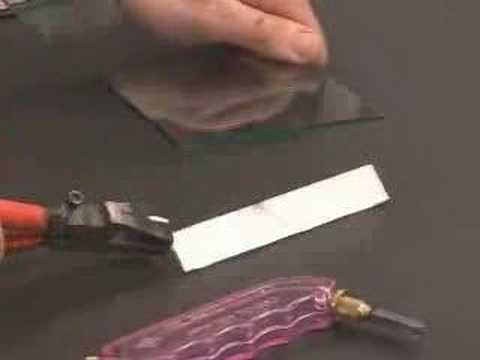
Educational video: Cutting Glass
A museum demonstration of glass cutting introduces scoring and controlled separation. It is educational context, not a machine operating procedure.