Kanger Glass-ceramic Co., Ltd.
A glass cutting CNC machine can automate a defined cutting or machining route, but the term covers different processes and does not establish what finished features a system can produce. First identify whether the proposal involves scoring, material-removal machining, or another cutting method. Then connect its capabilities to the actual substrate, thickness, geometry, edges, holes, print, and treatment sequence. For an appliance-panel order, the useful specification is the finished component and its inspection evidence. A machine model or a promotional cutting-speed figure is not proof that the requested glass part is feasible.
Identify the process behind the CNC label
CNC describes numerical control, not one universal glass-cutting mechanism. A controlled scoring table and a machining center can have very different tasks, tools, fixtures, and outputs. Ask the processor to explain which operation creates each feature on the drawing. Rectangular blank cutting, a shaped outer profile, an internal aperture, a drilled hole, and polished edges should not be bundled into an unexplained claim of automatic cutting.
Clarify which operations happen on the proposed system and which happen elsewhere. A cutting demonstration may show only a rough blank before grinding, washing, printing, and tempering. That can be a legitimate process route, but the quote should account for the complete part. Compare suppliers on the final requirement and evidence rather than assuming that the same machine category means the same finished capability.
Release the geometry in a controlled drawing package
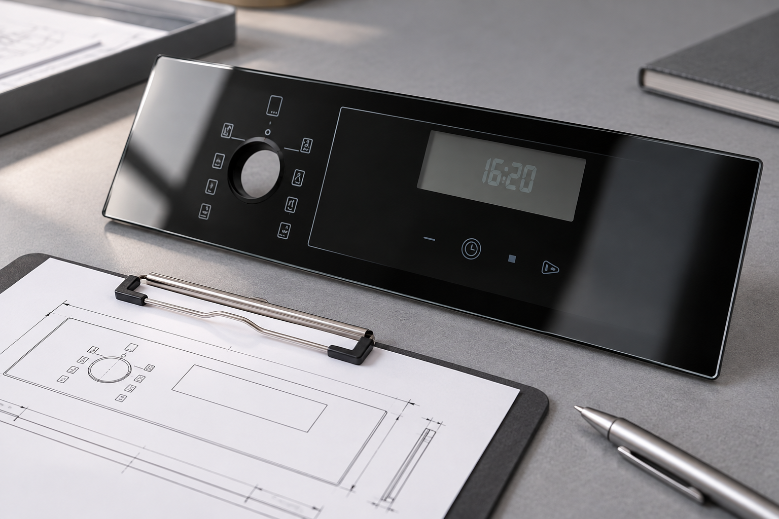
Provide the drawing revision, units, material, thickness, treatment, face orientation, datums, and final dimensions. Define holes, cutouts, corner transitions, edge profiles, and functional print areas where relevant. A CAD outline alone may omit the tolerances and surface requirements that determine whether the component is usable. Keep the graphical file and the written drawing consistent.
Agree on the file format the processor can use and which document controls when files disagree. Do not assume a conversion preserves every arc, spline, unit, or layer. The supplier should identify geometry that needs clarification before programming. If the design includes a sharp internal feature or another difficult detail, request a feasibility review rather than letting the programmer silently replace it with a different radius.
Distinguish the tool path from the finished boundary
The programmed path may need to account for a scoring offset, tool radius, kerf, finishing allowance, or another process-specific condition. Which compensation applies depends on the actual route. An OEM normally defines the finished geometry; the processor defines and validates the method that produces it. Avoid editing the customer’s CAD file into an undocumented manufacturing version that later returns as the supposed product drawing.
Keep manufacturing files tied to the released revision. If a programmer adjusts a path to correct a dimension, the change should be controlled within the process and verified on the output. A machine display showing the intended dimension does not measure the produced part. First-article inspection must still use the finished component and the agreed datum and measurement method.
Plan nesting without losing part identity
Nesting can arrange parts on a sheet for a proposed production route. Review material orientation, coated or printed faces, reference edges, separation space, and handling of the resulting blanks. Efficient sheet use is valuable, but it should not create an unreviewed orientation change or leave parts without the allowance needed by downstream operations. Ask what constraints the nesting plan applies to the actual material.
Keep part numbers and revisions identifiable through cutting and later processing. Similar profiles can be confused after separation, especially when several panel variants share a batch. The labeling or traveler method should avoid marking a functional surface with an unapproved material. If a layout is revised, make sure the production records still show which parts and quantities came from the relevant sheet or process batch.
Verify workholding and surface protection
The machine’s support and locating arrangement needs to suit the sheet and intended feature. Review clamps, vacuum support where applicable, pads, sacrificial surfaces, and the movement of offcuts. Do not infer that one attractive machine photograph establishes support for every size or coated face. The process trial should represent the relevant geometry and show whether contact marks or local damage occur.
Include loading, unloading, and intermediate transfers in the review. A correctly machined part can be damaged while it is moved to the next station. If holes, cutouts, or shaped edges reduce the rigidity of a blank, the handling arrangement needs to account for the actual component. The processor should identify the safe and repeatable method, rather than relying on an operator to improvise support for each new panel.
Qualify the complete fabrication sequence
For conventional thermal-tempered flat glass, cutting and required machining belong before heat treatment. NGA’s fabrication guidance warns against modifications after treatment because they may weaken or break the pane. Plan the process route accordingly and resolve feature changes before production tempering. A CNC system’s ability to machine an untreated sample does not establish routine post-tempering rework capability.
Check the final part after its relevant downstream operations. Edge finishing, washing, print, coating, and treatment can affect the acceptance result. Link the first article to the same drawing revision and route proposed for production. If a trial uses a different substrate, size, tool, or fixture, explain what it verifies and what remains unproven. A demonstration should have a defined scope rather than serving as broad evidence for all future orders.
CNC drawing and qualification checklist
| Area | Input to agree | First-article evidence |
|---|---|---|
| Process scope | Scoring, machining, or other route for each feature | Complete part contains the required features, not just a cut outline |
| Drawing package | Units, revision, datums, tolerances, and surface orientation | Inspection report uses the same released definition |
| File conversion | Accepted format and handling of arcs, layers, and conflicting files | Imported geometry is reviewed before production programming |
| Compensation | Process-specific path and finishing allowances | Produced dimensions meet the finished requirement |
| Nesting | Orientation, part identity, and downstream allowance | Variants remain identifiable and usable after separation |
| Workholding | Support, locating, contact protection, and offcut control | No unreviewed marks, deformation, or handling damage |
| Full route | Finishing, washing, print, treatment, and final inspection | Production-intent finished part meets the agreed acceptance plan |
This is a qualitative handoff table. Machine speed, accuracy, envelope, tooling, and material capability must come from the actual system and demonstrated process.
Choose inspection methods for the features that matter
Measure the outer profile, holes, cutouts, edge transitions, and relevant relative positions using methods appropriate to the requirement. A fit check in one bezel may be useful but can conceal dimensional differences if the fixture is not a controlled reference. Record how the part is supported and which datums are used. Preserve individual feature results when the assembly depends on their relationship.
NIST’s measurement-uncertainty guidance provides context for evaluating the reliability of these measurements. It does not establish the machine’s achievable tolerance or the customer’s acceptance limit. If the inspection method cannot resolve the requirement confidently, address that before releasing the trial. Avoid using the same unverified programmed coordinates as both the manufacturing definition and the independent proof that the part is correct.
Evaluate a machine proposal beyond throughput claims
Ask about material and feature range, setup changes, tool and fixture needs, inspection, maintenance, handling, and integration with downstream operations. A headline rate may describe a specific demonstration rather than the actual appliance part mix. Compare cycle definitions so loading, separation, tool changes, finishing, and inspection are not silently excluded from one supplier’s proposal.
If the OEM is purchasing finished glass rather than equipment, focus on confirmed delivery capability, part qualification, traceability, and change control. The processor’s machinery is relevant supporting information but does not replace the output specification. A supplier can propose a different route if it demonstrates the required finished result. The buyer should evaluate that proposal through the drawing and first article, not only the presence of CNC in the quotation.
Connect the inquiry to appliance-control glass
Send Kanger the finished geometry, substrate, treatment, surface system, expected order pattern, and required inspection evidence. Explain the module interface and any functional zones that make a feature critical. Ask which requirements are feasible and which need adjustment or qualification. Kanger’s appliance-panel page provides product context; it does not prove ownership of a particular CNC system or guarantee every requested profile.
Keep all agreed changes in the released drawing or controlled order documentation. If a profile is simplified, describe the change and verify its effect on fit and function. Requalify affected features when material, geometry, tool route, or surface conditions change. A controlled handoff helps turn an equipment-centered discussion into a concrete part order with a result that both supplier and buyer can inspect.
Frequently asked questions
Does every CNC glass cutter drill and polish?
No. CNC is a control description. Confirm the mechanism, tools, and actual operations available on the proposed system, including any separate downstream stages.
Is a CAD outline enough for an appliance panel?
Usually it also needs material, treatment, units, revision, datums, tolerances, surface orientation, edge finish, and feature requirements. Resolve conflicts before programming.
Can the programmed dimension replace inspection?
No. Measure the produced part using an appropriate method and the released drawing. A tool path is an instruction, not an independent measurement of the output.
What should a supplier demonstrate first?
A representative production-intent part covering the critical geometry, surface condition, full route, and acceptance method. State what the trial verifies and what remains outside its scope.
Related appliance-glass resources
- Thermal Shock Resisitance Tempared Glass For Household Appliances Panel Product
- Tempered Glass Appliance Panels: OEM Specification Guide
- Can Tempered Glass Be Cut? Limits, Risks, and Safer Alternatives
- How should a cooktop-panel drawing review a glass cutout?
Sources and further reading
- NGA — fabrication before heat treatment
- NIST — measurement uncertainty
- GGF Glazing Manual — architectural-glass context, not an appliance specification
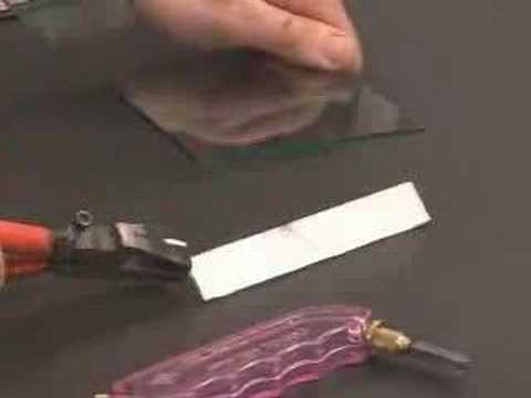
Educational video: Cutting Glass
A museum demonstration of glass cutting introduces scoring and controlled separation. It is educational context, not a machine operating procedure.