 Kanger Glass-ceramic Co., Ltd.
Appliance control panel glass drawing revision control should keep the glass outline, holes, printed artwork, display windows, touch zones, light masks, bonding areas, and inspection requirements aligned as one released configuration. Updating a PDF revision letter is insufficient if the print file, display module, or assembly fixture still represents the previous design. Define the change, review affected interfaces, obtain supplier acknowledgment, separate old and new stock, and verify the first production parts before releasing the revised panel.
This workflow focuses on control fascias and cover glass. It complements general cooktop-panel document control by addressing the functional relationship between a glass cover and its user-interface hardware and software. It does not assume that changing a symbol changes the electronics, or that unchanged glass dimensions make every artwork revision harmless.
Identify the full configuration
Create a controlled index of the part drawing, CAD outline, hole details, print artwork, colors or appearance references, transparent windows, coating specifications, mounting drawing, inspection methods, packaging instructions, and approved samples. Add the relevant display, sensor, illumination, and firmware references needed to interpret the interface. The glass supplier need not receive unrelated proprietary software, but it must receive enough controlled information to manufacture the specified component.
State which file governs each requirement. A vector artwork file can define icon geometry while the component drawing defines its position from datums. A photograph may illustrate appearance without defining scale. Avoid contradictory controlling dimensions in multiple files. Record the relationship among revisions instead of assuming every document will advance to the same letter at the same time.

Describe the change in functional terms
Mark what changes and why. A moved icon may need a matching sensor location; a new transparent window may need a revised display position; a changed print mask may alter unwanted light leakage. A new aperture may affect fabrication, mounting, cleaning, and measurement. Describe the intended result and affected region, not merely revised drawing.
Include a before-and-after view where it clarifies the change. Keep unchanged features identifiable, but do not clutter the release with ambiguous temporary annotations. Identify whether existing acceptance samples remain valid. If the color is unchanged but the symbol shape changes, the old sample may still be useful for color while becoming obsolete for artwork approval. Record those different purposes explicitly.
Check glass fabrication and edge consequences
Review outline, corner, aperture, thickness, and edge-process changes with the fabricator. Heat-treated glass fabrication normally precedes heat treatment, as the National Glass Association’s guidance explains. A revision that adds a hole should not be implemented by drilling finished tempered stock at the assembly site. Obtain an approved manufacturing disposition for existing parts.
Check the effect on tools, programs, fixtures, and inspection references. A hole moved relative to an edge can affect both the glass process and the control-knob alignment. A modified corner may require a new packing support or change the usable bonding area. Ask the supplier to report process implications and first-article needs instead of accepting an acknowledgment that only confirms receipt of the email.
Review display, touch, and illumination interfaces
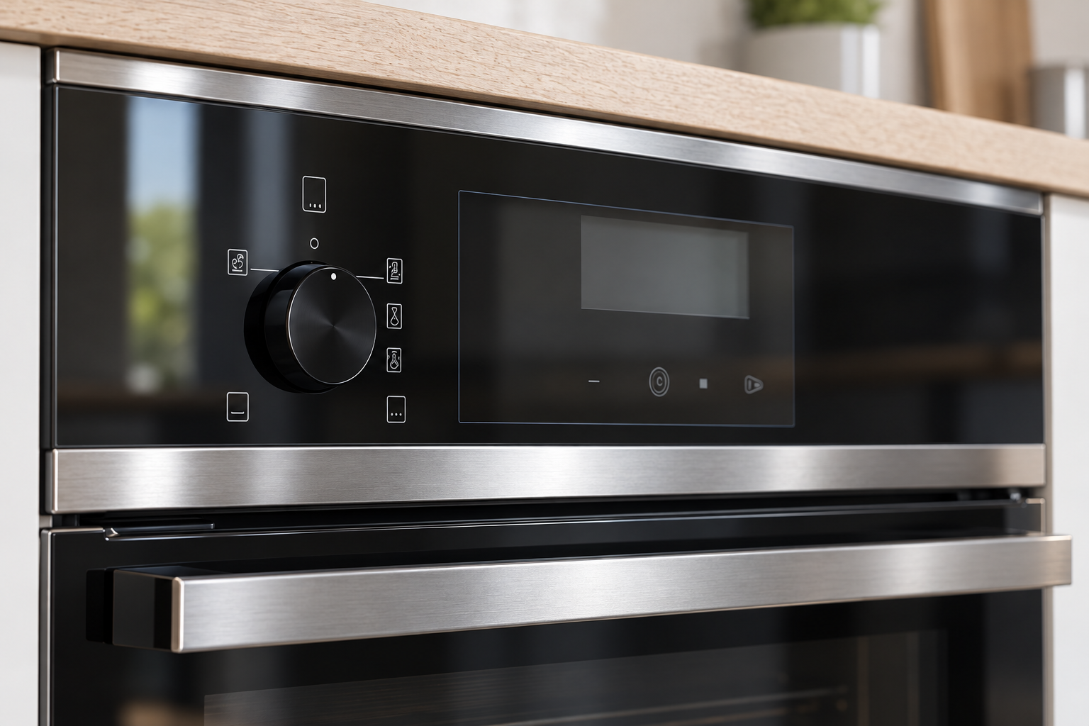
Confirm icon-to-sensor mapping with the appliance interface owner. A graphic that moves outside the responsive region can make a working control seem unresponsive. A larger print mask can obscure a display or change illumination appearance. A coating or substrate change may require review by the touch-system designer. Do not infer functional compatibility from an unchanged outside glass size.
Make the applicable module and firmware configuration visible in validation records. Inspect representative assemblies using the intended display, sensor support, light source, and operating mode. If only one variant changes, identify the variant and ensure shared artwork is not accidentally substituted. A panel family with several language or feature versions needs clear part identification so visually similar stock is not mixed.
Coordinate bonding and assembly changes
Review the adhesive or gasket path, retention arrangement, fixture contact areas, cure sequence, and assembly positioning method. Artwork can define an opaque bonding zone, so a print change may affect an interface even when it is presented as cosmetic. A new clear window can expose an adhesive bead or underlying component that was previously hidden.
Determine whether production instructions and inspection jigs need revision. Confirm that the assembly fixture does not contact new symbols, apertures, or unsupported regions. If a new version can fit an old fixture physically but aligns differently, define the prevention method. Relying on an operator to remember a subtle drawing difference is weaker than clear part identification and a controlled setup change.
Release one approved package
Use a controlled release location and a manifest that names the applicable files and their revisions. Mark the old package as superseded in the system while retaining it for traceability. Avoid sending several attachments with similar filenames and an instruction to use the latest one. Provide a clear effective point, affected order numbers, and supplier acknowledgment requirements.
Distinguish evaluation files from production files. A prototype drawing circulated for quotation should not automatically authorize serial manufacture. Record open issues and the person responsible for resolving them. If a change is partially approved, state exactly which work may proceed and which must remain on hold. Do not leave the supplier to interpret silence as approval of every proposed detail.
Use a change-impact matrix
| Changed item | Interface to review | Evidence before release |
|---|---|---|
| Outline or aperture | Housing, knob, tools and fixtures | Dimensional report and assembly fit |
| Printed icon | Sensor location and operating function | Artwork check and module interaction |
| Display window | Display alignment and visible border | Illuminated module inspection |
| Mask or coating | Light control, adhesion and appearance | Relevant optical and interface tests |
| Material or thickness | Processing, touch system and mounting | Exact material data and required validation |
| Packaging | Version separation and glass support | Pack identification and handling review |
Use this matrix as a review aid. It does not make every change equally significant or prescribe a universal test suite. The engineering owner should select validation based on the actual mechanism and scope of the change.
Decide what happens to existing stock
Count supplier stock, goods in transit, receiving stock, work in progress, and completed modules that may contain the old revision. Identify whether the new version is interchangeable and under which conditions. Do not assume interchangeability because both versions fit the bezel. A display or firmware difference can make an otherwise identical fascia incorrect for the appliance variant.
Record return, use-as-is, restricted use, approved rework, or disposal according to the responsible authority. Label accepted old-version stock with its permitted use. If rework is proposed, have the relevant glass, printing, and assembly specialists assess it. Do not use unapproved grinding, drilling, or graphic removal to turn finished panels into the new revision. Keep quantities and dispositions traceable.
Verify implementation on real production parts
Inspect first articles against the released package and retain their identities. Check the contour, apertures, print registration, windows, appearance, and other changed requirements with the agreed methods. NIST’s traceability guidance is relevant to documenting measurements; it does not replace the drawing’s limits. Verify module interaction where the change affects display, touch, or illumination.
After approval, confirm that production programs, print screens or files, fixtures, work instructions, inspection references, and packaging labels use the intended revision. Audit an early production sample rather than assuming the first-article approval proves every station changed correctly. For a Kanger request, include the complete change package, effective order, stock disposition, and required evidence so acknowledgment can lead to a controlled implementation.
Frequently asked questions
Is a new drawing revision letter sufficient?
No. Identify the controlling CAD, artwork, inspection, sample, and interface references. Confirm their compatibility and the supplier’s implementation. A revision letter on one file cannot prevent use of obsolete print or fixture data.
Can an icon change be treated as purely cosmetic?
Only after the relevant interface review. Icon position or meaning may relate to a sensor, display, illumination, or appliance variant. Verify the applicable hardware and operating configuration before approving the change.
Can old stock be used if the dimensions are unchanged?
Not automatically. Establish whether artwork, functions, material, appearance, and module compatibility remain acceptable. Record the authorized disposition and permitted appliance variant or order rather than mixing the stock informally.
What proves that the supplier implemented the revision?
Use first-article measurements, artwork and module checks, identified samples, and confirmation of updated production and inspection data. Review early production parts as well as the supplier’s written acknowledgment.
Related appliance-glass resources
Use the product overview to identify the component family and the engineering guides to define interfaces. These references support a drawing-led supplier discussion; they do not establish universal tolerances or replace validation of the intended appliance assembly.
- Thermal Shock Resisitance Tempared Glass For Household Appliances Panel Product
- Tempered Glass Appliance Panels: OEM Specification Guide
- How to Set Mounting Clearances for Appliance Control Panel Glass Under Thermal Expansion
- Designing the Sealing Interface Around Appliance Control Panel Glass
- How to Specify Durable Screen Printing on Appliance Control Panel Glass
Sources and method references
The linked references explain fabrication sequence, measurement principles or the stated inspection method. Apply their scope carefully: a general glass bulletin or instrument description is not certification of a Kanger part and supplies no project-specific acceptance limit.
- NGA: fabrication before heat treatment; general principle, not an appliance tolerance
- NIST: measurement uncertainty
- NIST: metrological traceability and fitness for purpose
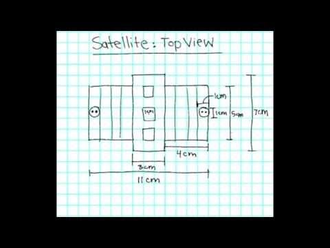
Educational video: Engineering Drawing Tutorial – NASA’s BEST Students
This educational introduction explains how drawings communicate geometry. It supports the specification and supplier-handoff discussion; it is not a glass-processing instruction or a calibrated inspection method.
Watch Engineering Drawing Tutorial – NASA’s BEST Students from NASA BEST Students


