Kanger Glass-ceramic Co., Ltd.
Appliance control panel glass optical inspection should evaluate the finished fascia by functional zone and viewing condition. Separate opaque printed areas, transparent display windows, illuminated icons, and customer-visible glass surfaces. Define lighting, background, viewing distance, orientation, reference samples, and defect classification before accepting a batch. A black panel can look acceptable with its display off yet reveal uneven transmission, unwanted light leakage, or a visible defect when the module is illuminated.
This inspection concerns appearance and optical function of a control cover. It does not certify touch performance, glass strength, or appliance electrical safety. Those require their own validated methods, and a cooktop glass-ceramic appearance specification should not automatically replace the requirements for a tempered control fascia.
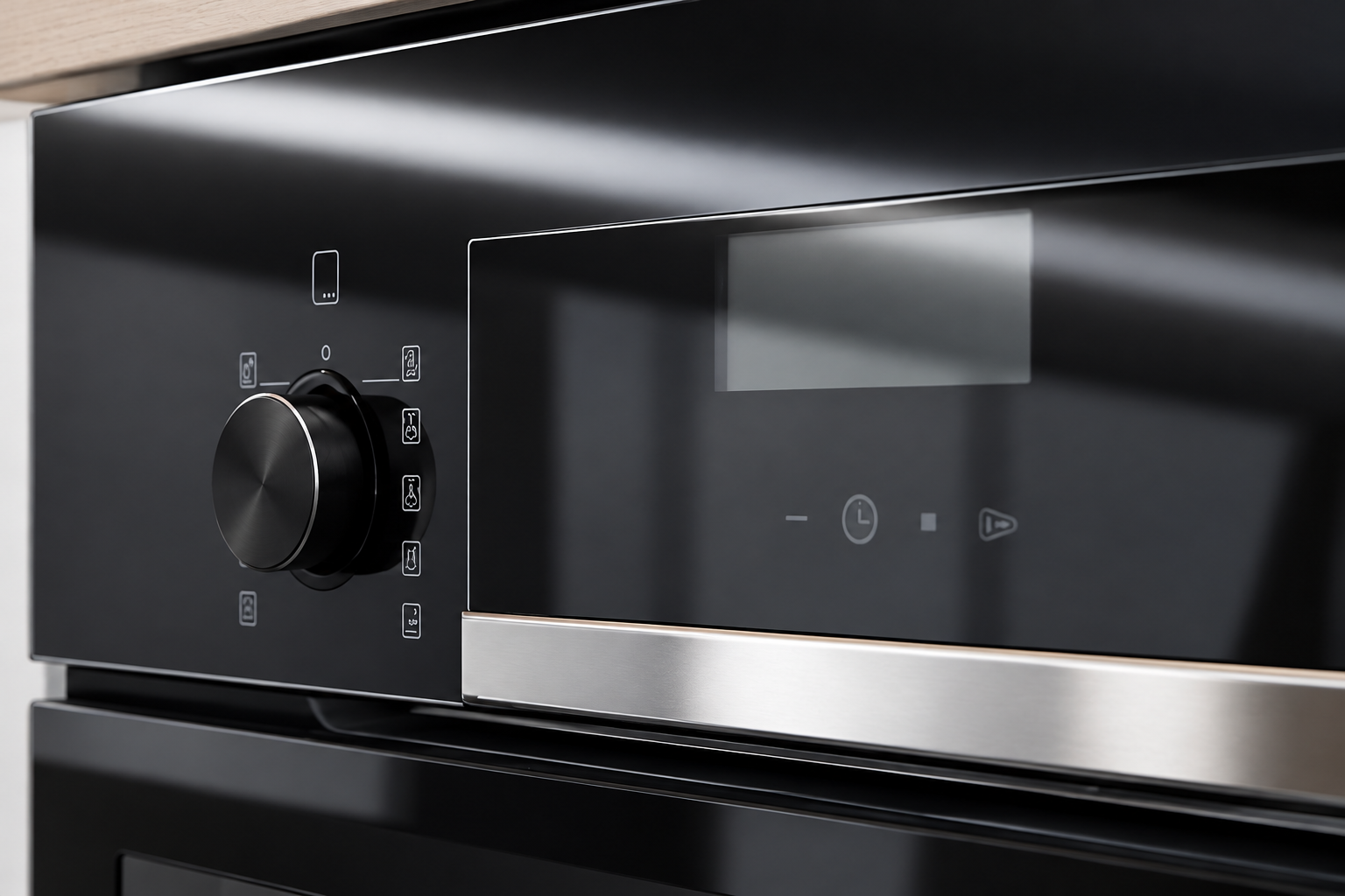
Divide the panel into meaningful inspection zones
Mark the display window, printed mask, illuminated symbols, rotary-control area, visible border, concealed edge, and bonding region on a controlled view. Identify which defects matter in each zone. A pinhole in a light-blocking mask can be highly visible during operation, while a similar mark in a concealed border may have a different agreed classification. An inspection rule that treats every square of the panel identically often misses functional differences.
Keep zone definitions linked to the artwork and assembly revision. When the display moves or an icon becomes illuminated, its inspection requirement may change even if the glass outline remains identical. Include both viewing-face and print-face information so a receiving inspector does not judge hidden process marks as customer-visible defects or overlook damage on a functional printed layer.
Standardize lighting and observation
Define the inspection light source, background, viewing distance, viewing angle, and time allowed for inspection. Specify whether examination occurs with the display off, on, or both. Use representative module illumination for transmitted-light checks. A bright flashlight held immediately against the panel can reveal marks that are irrelevant to normal appearance and may not reproduce the intended acceptance condition.
Maintain the setup at supplier and receiving locations. Document lamp condition and replace or verify it according to the agreed procedure. Avoid uncontrolled reflections from windows or overhead lights. If a viewing jig is used, check that it does not scratch the panel or conceal the edge under evaluation. Photograph the setup itself so future operators can reconstruct the conditions behind an approved sample.
Clean consistently before classifying defects
Surface contamination can resemble haze, staining, scratches, or coating damage. Inspect the as-received condition first when packaging contamination is part of the question. Then use the approved cleaning procedure and inspect again, recording the difference. Do not use an unapproved solvent or abrasive to make a sample appear acceptable. That can change printed layers, coatings, or glass surfaces and destroy evidence.
Control cloth cleanliness, handling gloves, and contact surfaces. If a mark disappears after approved cleaning, record contamination rather than classifying it as a permanent optical defect. If it remains, map its location and determine which surface or layer contains it. Retain a suspect sample before repeated cleaning. An inspection team should not polish away a disputed mark and then request a supplier investigation of the original condition.
Assess color and opacity separately
For opaque masks, distinguish color match, gloss appearance, print coverage, and light-blocking behavior. A color reference approved under one light source may look different under another. Use the agreed appearance reference and, where specified, the agreed color-measurement method. Record the instrument geometry and setup rather than comparing unexplained numbers from different devices.
Check opacity in the intended illuminated assembly. Examine icon boundaries, print edges, and any transitions near a display opening. A panel may have consistent dark appearance in reflected light but transmit light unevenly. Do not infer transmission behavior from the color name. If instrument readings are required, obtain the appropriate method and acceptance limits from the released specification; this guide does not assign universal optical values to Kanger panels.
Investigate haze in the correct layer
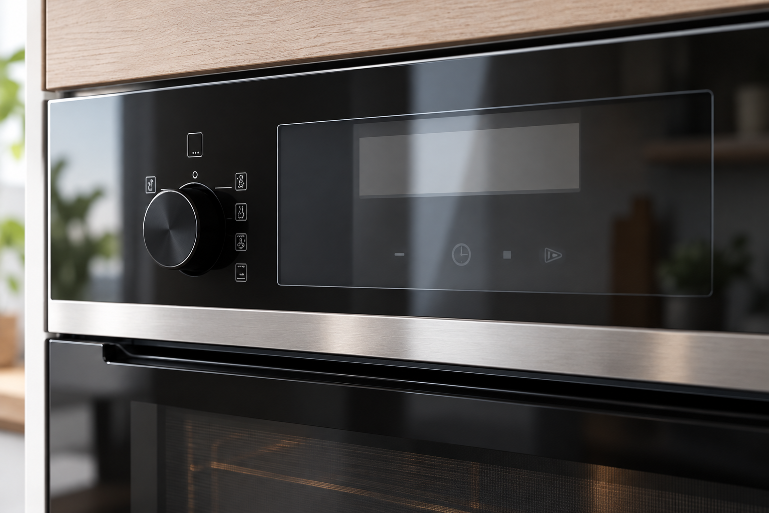
Haze is a descriptive observation unless a specified method gives it a measured meaning. Determine whether the effect belongs to surface contamination, the substrate, a coating, a print layer, an adhesive, or the display module beneath the cover. Compare the loose panel and the assembled module under controlled conditions. A problem visible only after bonding may require an interface investigation rather than a glass rejection.
Use a clear window and a suitable reference target where transmission is relevant. Record whether the symptom changes with viewing angle or illumination. Optical instruments must be suitable for the panel’s transparency and geometry. A heavily printed or curved specimen may not fit an otherwise useful method. NIST’s measurement guidance supports defining the complete method and uncertainty; a familiar instrument name alone does not establish a valid optical acceptance test.
Map scratches, inclusions, pinholes, and chips
Record location, observed size under the agreed method, surface or layer, and defect type. Distinguish scratches in glass from marks in a printed coating. Distinguish a mask pinhole from a designed transparent feature. Check edge chips separately because their significance can extend beyond appearance. Do not use an optical pass to overrule a dimensional or structural nonconformity.
Where visual boundary samples are used, preserve their identity and condition. Define who can approve replacements if a sample degrades. Include photographs as supporting records, but remember that camera exposure and magnification can change apparent severity. A photograph without scale and viewing conditions cannot automatically replace the agreed inspection method. Escalate uncertain classifications rather than creating a new rule in the middle of a receiving lot.
Use a zone-based inspection sheet
| Zone or observation | Inspection condition | Record needed |
|---|---|---|
| Opaque mask | Controlled reflected light and background | Color reference, coverage and surface marks |
| Display window | Defined transmitted-light or module view | Haze, inclusions, clarity and location |
| Illuminated icon | Production-intent light source | Light leakage, boundary and uniformity |
| Visible border | Agreed viewing distance and angle | Scratches, print registration and appearance |
| Concealed bonding area | Process and interface inspection | Contamination or damage affecting adhesion |
| Glass edge | Separate edge criterion and method | Chips, sharp remnants and affected location |
The table identifies different decisions rather than numerical defect limits. Complete it with the project’s released criteria and reference samples. If a zone does not apply, mark it explicitly instead of silently skipping it.
Compare supplier and receiving judgments
Select a reference group with clear passes, clear failures, and borderline examples. Have trained operators at both sites classify the same samples using the same conditions. Compare disagreements by zone and defect type. If one site sees light leakage only because it uses an unintended lamp, resolve the method first. If observers use different defect definitions, revise the classification guidance and retrain before comparing rejection rates.
Keep optical inspection separate from a sampling decision. The inspection method determines whether a examined unit conforms; the sampling plan determines how the resulting observations affect a lot. A consistent sampling table cannot compensate for inconsistent visual judgment. Record the sample selection, unit identities, inspector, method revision, and disposition so the supplier can reproduce the investigation.
Validate the assembled display and control interface
Check representative panels over production-intent displays, lights, sensors, and mounting layers. Evaluate normal operating views and the conditions required by the appliance validation program. Verify that apparent optical changes are not caused by a display setting, diffuser, uneven illumination, adhesive void, or module misalignment. Keep the glass observation and the module-function observation as separate results.
For development or sourcing, send Kanger the zone drawing, artwork, appearance reference, illumination description, inspection method, and intended assembly context. Ask for samples and evidence for the specific panel configuration. Do not request generic perfect black glass without explaining what the mask and transparent regions must do. A clear optical agreement helps procurement compare samples and gives quality teams a reproducible acceptance decision.
Frequently asked questions
Can a control panel be inspected only with the display off?
Not when transmitted-light features matter. Inspect the relevant display and illuminated-icon regions in the defined operating condition as well as reflected light. Record the module setup so the judgment can be repeated.
Does visible haze necessarily come from the glass substrate?
No. Contamination, coating, printing, adhesive, or the display beneath the cover may contribute. Compare approved cleaning, loose-panel inspection, and assembled-module observations before identifying the affected layer.
Can photographs replace approved limit samples?
Only if the specification validates that method. Exposure, lighting, scale, and magnification affect a photograph’s appearance. Use photographs to document location and observations while retaining the agreed physical reference and viewing conditions.
Does an optical pass prove that the panel is safe and functional?
No. Optical inspection evaluates the specified appearance and optical characteristics. Edge integrity, dimensions, touch response, thermal behavior, and appliance safety remain separate requirements with their own appropriate verification.
Related appliance-glass resources
Use the product overview to identify the component family and the engineering guides to define interfaces. These references support a drawing-led supplier discussion; they do not establish universal tolerances or replace validation of the intended appliance assembly.
- Thermal Shock Resisitance Tempared Glass For Household Appliances Panel Product
- Tempered Glass Appliance Panels: OEM Specification Guide
- How to Set Mounting Clearances for Appliance Control Panel Glass Under Thermal Expansion
- Designing the Sealing Interface Around Appliance Control Panel Glass
- How to Specify Durable Screen Printing on Appliance Control Panel Glass
Sources and method references
The linked references explain fabrication sequence, measurement principles or the stated inspection method. Apply their scope carefully: a general glass bulletin or instrument description is not certification of a Kanger part and supplies no project-specific acceptance limit.
- NGA: fabrication before heat treatment; general principle, not an appliance tolerance
- NIST: measurement uncertainty
- NIST: metrological traceability and fitness for purpose
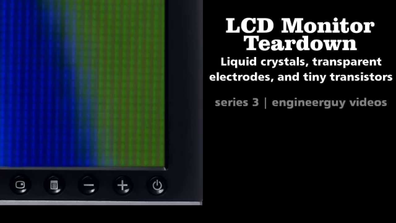
Educational video: LCD Monitor Teardown
Bill Hammack explains the display, backlight and optical layers in an LCD monitor. This helps distinguish cover-glass observations from module effects; an appliance cover is not the LCD cell, and the video sets no acceptance limits.