 Kanger Glass-ceramic Co., Ltd.
A laser glass thickness gauge should be selected for the actual substrate, transparency, printed zones, coatings, access, and measurement task. A laser displacement sensor does not automatically measure glass thickness. Some systems measure two opposing surfaces; other optical systems identify interfaces from one side under defined material conditions. Before purchasing or accepting readings, establish which surfaces the system detects and validate it on representative finished appliance panels against a suitable reference method.
This guide focuses on choosing and qualifying a non-contact measurement system. The separate guide on measuring glass thickness covers general contact and optical methods. Here the main decision is whether a proposed optical instrument can give reliable, useful results on the production part and at the intended measurement locations.
Define the measurand before the instrument
State whether you need substrate thickness, total coated thickness, a layer thickness, an assembled gap, or surface displacement. These are different quantities. A sensor may accurately report the distance to the front surface while providing no information about the rear surface. A system that detects several interfaces needs a defined rule for choosing the pair that represents the desired layer.
Locate the measurements on the component drawing. A transparent display window, black printed mask, coated area, and bare edge may give different optical returns. If the acceptance specification applies to substrate thickness, determine how the method will distinguish that substrate from layers added afterward. Keep the requested value and the instrument’s reported output explicitly connected in the qualification record.
Understand the proposed optical arrangement
Ask whether the system uses opposing displacement sensors, a one-sided interface method, or another defined principle. With an opposing arrangement, the instrument combines measurements of the two surfaces with a controlled reference separation. Alignment and the stability of that separation become part of the result. A brochure that lists only sensor resolution leaves those system effects unresolved.
Confocal chromatic systems can measure suitable transparent layers by detecting optical interfaces under the instrument’s defined conditions. The technology is not interchangeable with every device marketed as a laser gauge. Micro-Epsilon’s technical description distinguishes one-sided confocal thickness measurement from two-sided laser arrangements. Use that distinction to question proposals, without assuming one named method will work through every opaque mask or on every appliance substrate.
Test transparent, printed, and coated regions
Supply representative samples covering the actual part variations. Include clear windows, opaque masks, print boundaries, coatings, and relevant thickness conditions. Ask for raw signal evidence and the selected-interface configuration where the system provides it. A stable numerical result is insufficient if the instrument repeatedly selects the wrong optical peak or the printed surface instead of the intended glass interface.
Test transitions between zones if the system scans across them. Determine what happens when a reading is invalid: does the software flag it, hold the previous value, substitute another interface, or output a plausible-looking number? An invalid reading that silently becomes a passing thickness result is a significant qualification concern. Define the handling of missing data before using the system for acceptance or process control.
Control material and calibration inputs
One-sided optical thickness methods may require material-specific configuration or compensation according to their operating instructions. Confirm the exact substrate information needed and how it is entered, verified, and protected against accidental changes. Do not use a generic transparent-glass setting without determining its applicability to the actual material and conditions.
Use suitable calibrated reference specimens and a documented verification method. NIST’s traceability guidance emphasizes the connection between a measurement result and its reference, with uncertainty in that chain. A claim that the sensor is calibrated does not by itself demonstrate that the complete setup is fit for the panel’s acceptance decision. Record the reference identity, calibration scope, condition, and verification result for the assembled measurement system.

Examine mounting, motion, and environmental effects
Specify fixture stability, sensor alignment, standoff, panel support, motion speed, and vibration conditions relevant to use. For a scanning or inline system, a stationary bench trial may not reproduce production motion. Evaluate representative operating conditions rather than accepting the best result obtained during a carefully arranged demonstration.
Review temperature, ambient light, contamination, and surface condition within the instrument manufacturer’s specified operating limits. A dusty window or fixture shift can change readings or signal quality. Define cleaning and verification intervals based on actual system use. Avoid directing operators to compensate unexplained drift with an arbitrary offset. Investigate the reference, setup, and signal before changing the configuration.
Compare the complete system with a reference method
Select an appropriate comparison method for the actual measurand and part. A contact micrometer may be useful at accessible bare locations, but it may measure a different layer stack or position from the optical system. Match the location and quantity before calling a disagreement an instrument error. Preserve actual paired readings and the limitations of the comparison.
Repeat removal and replacement of specimens, include different operators where relevant, and evaluate the intended setup changes. NIST’s uncertainty guidance supports considering these contributions in addition to sensor repeatability. Do not equate resolution, repeatability, and accuracy. A gauge that repeats the same wrong-interface reading is repeatable without being suitable for thickness acceptance.
Use a qualification checklist
| Question | Evidence required | Why it matters |
|---|---|---|
| What quantity is measured? | Defined surfaces, layers and drawing locations | Prevents accepting displacement as thickness |
| Which zones are measurable? | Clear, printed and coated sample trials | Exposes material-dependent limitations |
| How are interfaces selected? | Signal and software configuration records | Prevents plausible wrong-layer readings |
| How is the system verified? | Reference method and calibration traceability | Links readings to an acceptance decision |
| What happens to invalid data? | Flags, rejection logic and stored raw status | Prevents silent substitution of missing values |
| Does production change the result? | Motion, fixture and environment trials | Tests the actual intended application |
The checklist is independent of a particular instrument brand. Request the evidence rather than assuming that a quoted accuracy specification applies to every configuration or surface.
Define a meaningful measurement map
Choose locations based on the drawing and functional requirement. Do not measure only a clear display window if the specified characteristic applies to the entire pane and other regions may differ. Conversely, do not claim substrate variation from a map that crosses printed layers without a validated way to remove their contribution. State excluded zones and the alternative checks used there.
For a scanning system, document sampling interval, scan path, position registration, filtering, and how outliers are handled. Aggressive smoothing can hide a local feature; inadequate signal filtering can create false variation. Preserve raw data when possible and keep processing settings under revision control. A color map without scale, coordinates, and processing information is difficult to use in a supplier dispute or engineering investigation.
Connect procurement and receiving requirements
Ask the instrument supplier for a sample trial, proposed configuration, installation requirements, software behavior, calibration and service plan, training, and a documented acceptance demonstration. Include the actual part family and intended throughput. Evaluate the cost and practical burden of fixtures, reference specimens, integration, and ongoing verification along with the sensor price.
For glass sourcing, agree whether Kanger and the receiving facility will use the same system or validated different methods. Send the panel drawing, material identity, coatings and printing, measurement map, and acceptance rule. Keep thickness measurements separate from flatness and optical appearance checks. A capable non-contact gauge supports a specific inspection task; it does not certify every property of a finished appliance panel.
Frequently asked questions
Can any laser displacement sensor measure glass thickness?
No. Distance to one surface is not thickness. The system must identify or measure the relevant surfaces and apply its defined geometry or material model. Validate the proposed arrangement on the actual finished panel.
Will a one-sided optical gauge work through opaque printing?
Do not assume so. Test the actual print and substrate configuration using the instrument’s operating instructions. Some zones may require another method or may be excluded from the qualified optical measurement map.
Is a very small displayed resolution enough for acceptance?
No. Assess calibration, interface selection, positioning, temperature, repeatability, and the uncertainty of the complete measurement. A precise-looking number can still describe the wrong surface or contain a systematic error.
What should be saved with each thickness map?
Save part and revision identity, locations, fixture and sensor configuration, calibration references, material settings, signal validity, processing parameters, and the acceptance decision. Retain raw data where practical so results can be reviewed later.
Related appliance-glass resources
Use the product overview to identify the component family and the engineering guides to define interfaces. These references support a drawing-led supplier discussion; they do not establish universal tolerances or replace validation of the intended appliance assembly.
- Thermal Shock Resisitance Tempared Glass For Household Appliances Panel Product
- Tempered Glass Appliance Panels: OEM Specification Guide
- How to Set Mounting Clearances for Appliance Control Panel Glass Under Thermal Expansion
- Glass Coating Machines: Process Questions for Functional Appliance Glass
- How to Specify Durable Screen Printing on Appliance Control Panel Glass
Sources and method references
The linked references explain fabrication sequence, measurement principles or the stated inspection method. Apply their scope carefully: a general glass bulletin or instrument description is not certification of a Kanger part and supplies no project-specific acceptance limit.
- Micro-Epsilon: optical thickness principles; sensor-maker technical reference
- NIST: measurement uncertainty
- NIST: metrological traceability and fitness for purpose
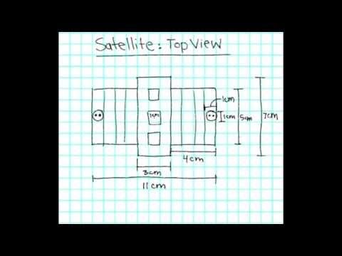
Educational video: Engineering Drawing Tutorial – NASA’s BEST Students
This educational introduction explains how drawings communicate geometry. It supports the specification and supplier-handoff discussion; it is not a glass-processing instruction or a calibrated inspection method.
Watch Engineering Drawing Tutorial – NASA’s BEST Students from NASA BEST Students


