 Kanger Glass-ceramic Co., Ltd.
Appliance control panel glass flatness tolerance needs a defined surface, support condition, measurement method, and acceptance criterion. A fascia that looks curved under a reflected ceiling light is not automatically dimensionally unacceptable. A panel that measures acceptably on a bench can still rock on a housing, produce an uneven adhesive gap, or misalign with a display. Measure loose-glass geometry and assembled-module behavior as separate characteristics, then connect both to the released drawing and actual functional requirements.
This guide concerns control-cover glass, including tempered appliance fascias. It does not prescribe a universal flatness value or substitute the specification of glass-ceramic cooking panels for that of the actual component.
Define what the word flatness refers to
Distinguish global bow, local waviness, twist, surface profile, and assembly seating. These observations may overlap visually, but they are not interchangeable measurements. Specify the characteristic being accepted and its evaluation region. A display window may have a different functional requirement from an opaque printed margin. A retaining gasket may accommodate a shape that a rigid adhesive spacer cannot.
Avoid accepting the part solely by the phrase lies flat. The answer depends on which face rests on which supports and whether the panel is pushed into contact. Define whether measurement is free-state, supported on prescribed points, or performed in the assembled condition. If an applied load belongs to the method, record it. Otherwise, an inspector may unintentionally flatten the glass while attempting to measure it.

Distinguish substrate shape from optical appearance
A reflected line is a useful screening tool for surface distortion, but it also depends on viewing angle, light geometry, coatings, and the surface being observed. Use a repeatable viewing arrangement if reflection appearance is an acceptance characteristic. Do not turn a photograph of a bent reflection into a numerical flatness report without a calibrated method.
Transparent windows, dark print, bevels, and multiple reflecting interfaces complicate optical measurement. An instrument may detect the printed surface in one region and the glass surface in another. Determine which interface it measures before comparing results. A coating-thickness change can affect a surface reading without representing a corresponding change in the substrate’s overall shape. Preserve appearance observations separately from dimensional data.
Specify supports and orientation
Support arrangement can change the observed shape of a thin or long pane. Document support locations, contact materials, orientation, measurement face, and whether the panel is horizontal or vertical. Avoid an improvised fixture that forces contact around the full perimeter unless that condition is intentionally being evaluated. Clean supports and check that particles are not lifting the panel locally.
Record how the part is positioned against the datum system. Place and remove representative specimens several times to test whether repositioning changes the result. If the reading is sensitive to the support arrangement, that sensitivity needs investigation rather than averaging it away. Supplier and receiving laboratory should use the same controlled method or establish an agreed correlation between methods with a documented limitation.
Select a method for the actual characteristic
Possible methods include a defined gap measurement, contact displacement mapping, optical profile scanning, or coordinate measurement, depending on the component and requirement. Select the method by the surface and evaluation region, not by the number of digits shown on the instrument. A few measurements along an edge do not necessarily reveal a localized problem in a display region.
For a point map, define spacing and include locations where the assembly is sensitive. State how the reference plane is constructed and whether edge zones are excluded. For a line scan, record direction and sampling. For optical methods, validate interface detection on the actual printed and coated panels. NIST’s uncertainty guidance supports assessing the whole setup, including repositioning, calibration, operator effect, and environmental conditions.

Establish limits from function and manufacturing evidence
Begin with what the module needs: seating, controlled adhesive thickness, display alignment, cosmetic appearance, touch response, or sealing. Evaluate how panel geometry and housing geometry combine. A tight glass-only limit may not solve a distorted bezel; a loose limit may transfer unacceptable variation to an adhesive process. Define the component limit together with the interface design.
Discuss process capability with the fabricator using representative parts and the agreed measuring method. Request actual measurement distributions rather than a vague statement that the process is high precision. Do not confuse capability evidence with permission to change a drawing limit. If the design and process do not overlap acceptably, review the design, process, measurement, or sourcing decision before approving production.
Measure before and after assembly where necessary
Loose-part inspection helps distinguish supplied geometry from assembly-induced behavior. Measure representative panels, record their identities, and then assemble them with production-intent housings, adhesives, spacers, and fixtures. Check the resulting gaps and alignment at the same meaningful locations. Keep the measurement history linked to each panel rather than reporting unrelated loose and assembled averages.
If a panel becomes visibly distorted after assembly, inspect fixture loading, housing geometry, adhesive placement, curing, and local hard contacts. Do not immediately request flatter glass. A fixture that presses the center while holding the ends can conceal a process problem until it is removed. Conversely, a housing that is acceptable at room temperature may require further evaluation under the appliance’s validated thermal duty.
Use a measurement agreement
| Characteristic | Method detail to agree | Functional connection |
|---|---|---|
| Global shape | Surface, reference plane and evaluation region | Overall module seating |
| Local profile | Scan locations and spatial sampling | Display window or sensor support |
| Twist | Corner locations and support arrangement | Unequal corner gaps |
| Reflection appearance | Viewing angle, light pattern and distance | Customer-visible distortion |
| Assembled gap | Module condition and fixture release state | Adhesive, gasket and bezel fit |
This agreement is a method checklist. It does not contain appliance acceptance limits. The project’s drawing and validation evidence should supply those values and state how results near a boundary will be handled.
Check repeatability and disagreement
Run a practical comparison using the same specimens at the supplier and receiving facility. Include panels with different measured shapes and appearance conditions. Compare both numerical results and contour patterns. If one laboratory excludes a printed edge while another includes it, a difference may come from the evaluation region rather than instrument error. Align the definitions before changing calibration or blaming operators.
Assess repeated placement, different operators, and relevant environmental changes. Report the uncertainty suitable for the decision. Resolution, repeatability, and accuracy describe different aspects of measurement. A stable display value can still contain a systematic offset. When disagreement remains, quarantine the affected acceptance decision and arrange a documented comparison; do not select whichever measurement happens to pass the lot.
Keep inspection and supplier requests traceable
The report should identify panel drawing, batch, sample, measuring equipment, calibration, software setup, supports, temperature condition, evaluated region, raw readings, and decision. Retain contour plots or scan data when they explain a localized feature better than a summary number. Keep the original data if a revised analysis is performed. A new calculation should not overwrite the evidence behind the first decision.
For a quotation or development request, send the glass drawing and the module interface information with the proposed flatness method. Explain the functional reason for the requirement and ask whether the supplier can measure and manufacture it consistently. Kanger’s appliance glass product family provides the component context; a particular acceptance limit requires agreement on the actual panel and assembly.
Frequently asked questions
Does a distorted reflection prove the panel fails its flatness tolerance?
No. Reflection appearance is influenced by viewing conditions and surface characteristics. Use it for a defined appearance assessment or screening, then apply the agreed dimensional method to determine whether the specified geometry is acceptable.
Should a panel be clamped flat during inspection?
Only if that loaded condition is explicitly part of the specification. Unspecified clamping can hide free-state shape and make results incompatible with supplier measurements. Record supports, loads, orientation, and evaluation region.
Is glass flatness the same as the assembled bezel gap?
No. The gap also depends on housing geometry, spacers, adhesive, positioning, and assembly loading. Measure both when needed and trace results to the same specimens to identify where the variation originates.
What is a suitable universal tolerance?
There is no universal value here. Establish the requirement from the module’s function, actual material and process capability, validated assembly behavior, and a measuring method with adequate uncertainty for the acceptance decision.
Related appliance-glass resources
Use the product overview to identify the component family and the engineering guides to define interfaces. These references support a drawing-led supplier discussion; they do not establish universal tolerances or replace validation of the intended appliance assembly.
- Thermal Shock Resisitance Tempared Glass For Household Appliances Panel Product
- Tempered Glass Appliance Panels: OEM Specification Guide
- How to Set Mounting Clearances for Appliance Control Panel Glass Under Thermal Expansion
- Designing the Sealing Interface Around Appliance Control Panel Glass
- How to Specify Durable Screen Printing on Appliance Control Panel Glass
Sources and method references
The linked references explain fabrication sequence, measurement principles or the stated inspection method. Apply their scope carefully: a general glass bulletin or instrument description is not certification of a Kanger part and supplies no project-specific acceptance limit.
- NGA: fabrication before heat treatment; general principle, not an appliance tolerance
- NIST: measurement uncertainty
- NIST: metrological traceability and fitness for purpose
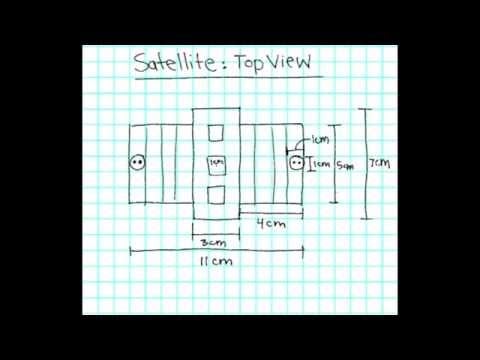
Educational video: Engineering Drawing Tutorial – NASA’s BEST Students
This educational introduction explains how drawings communicate geometry. It supports the specification and supplier-handoff discussion; it is not a glass-processing instruction or a calibrated inspection method.
Watch Engineering Drawing Tutorial – NASA’s BEST Students from NASA BEST Students


