 Kanger Glass-ceramic Co., Ltd.
An appliance control panel glass thermal shock test should reproduce the relevant temperature changes of the finished control module and measure both glass integrity and module function. Define the glass material, print system, mounting, adhesive or gasket, electronics, initial condition, temperature history, and acceptance criteria before choosing a test cycle. Passing a test on a loose pane does not establish that the same pane will work when restrained in a housing or bonded over a touch sensor.
This guide addresses control fascias and display covers. It does not transfer the thermal properties of a glass-ceramic cooking surface to tempered appliance glass. Actual limits must come from the application requirements, exact material data, applicable appliance requirements, and a documented validation program.
Translate the appliance duty into a test question
Start by asking what event the design must withstand. A control strip beside an oven door may experience heat from the appliance and cooling after use. A washing-machine interface may face humidity and temperature changes of a different kind. A cold liquid contacting a hot surface is another event again. These are different exposures, and one convenient chamber cycle should not stand in for all of them without justification.
Map the intended use, foreseeable cleaning, installation environment, and abnormal conditions that the responsible appliance team must evaluate. Separate a routine qualification question from an investigation of a reported failure. Qualification needs predefined criteria and representative samples. Investigation needs preserved evidence and controlled hypotheses. Combining the two without a clear purpose can produce results that neither approve a product nor explain the complaint.
Identify the exact test article
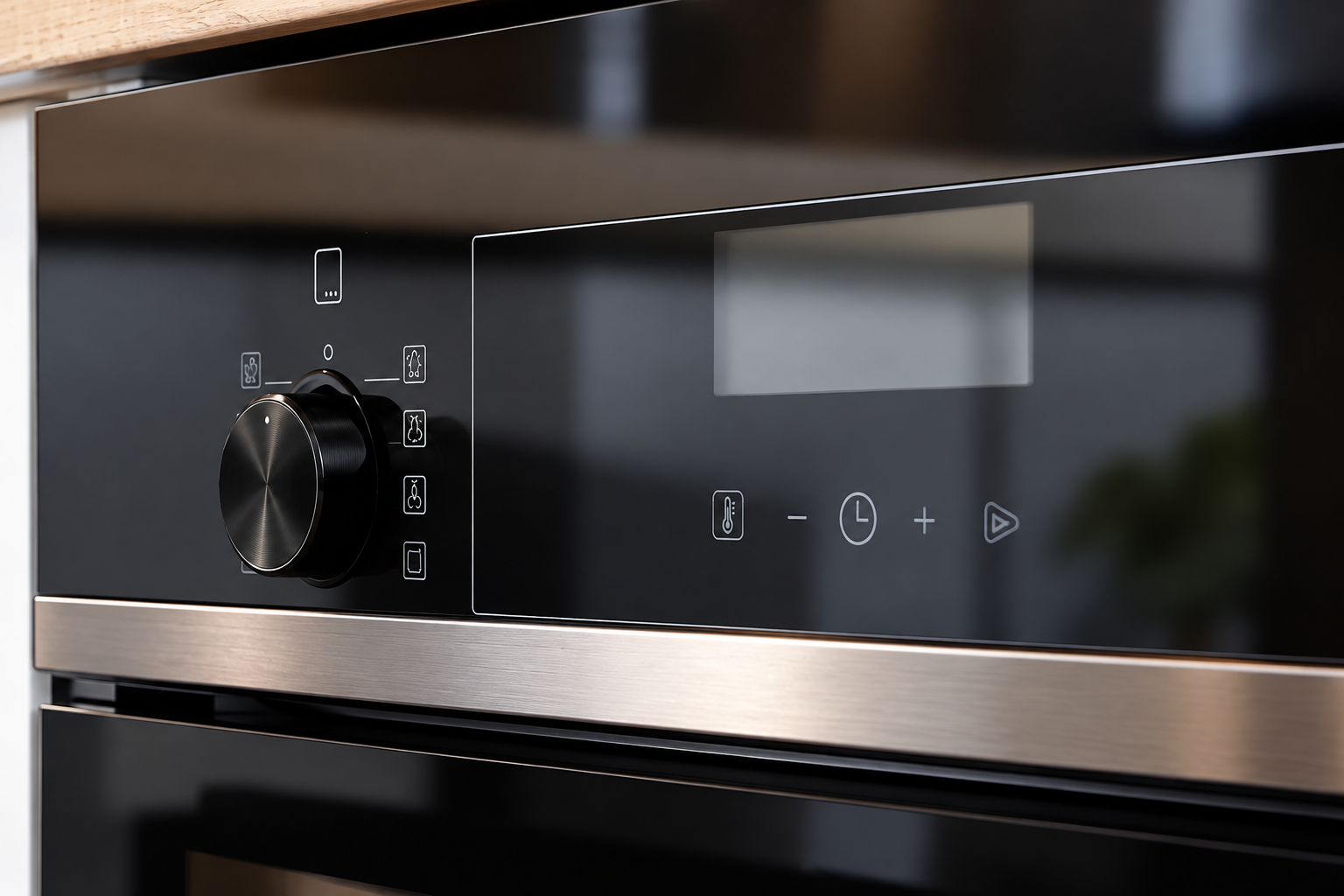
Record material designation, supplier, thickness, dimensions, edge features, holes, heat-treatment condition, print face, ink or coating system, and drawing revision. Include the panel’s traceability to fabrication and printing batches. A description such as black glass omits too much. The visible appearance alone cannot establish whether a component is tempered glass, glass-ceramic, or another substrate.
Describe the assembly as carefully as the pane. Record the housing, fastening method, gasket, adhesive, cure condition, sensor support, display position, and gap arrangement. If production uses a changed adhesive or different support, the old test may no longer represent the current module. Keep photographs and a bill of materials with the test record so an engineer can reconstruct the tested condition months later.
Measure where the temperature actually matters
Chamber air temperature is not necessarily glass temperature. Place appropriately selected sensors at meaningful locations, such as a heated boundary, an exposed face, a shielded region, or an assembly interface. Justify sensor attachment and assess whether it changes the local condition. Record the control variable and measured temperatures separately. A timer that starts when chamber air reaches a setpoint may start before the specimen reaches the intended state.
Measure the differences between locations where the risk depends on a gradient. A nearly uniform hot pane and a pane with a hot edge and cool center can present different loading conditions. Do not infer the gradient from one sensor. Document sampling rate, sensor identity, calibration, attachment, and any unavailable location. NIST’s measurement guidance is useful for planning uncertainty; it does not prescribe a safe appliance operating temperature.
Specify the exposure sequence explicitly
The procedure should state preconditioning, starting condition, heating or cooling method, transition timing, dwell criterion, number of repetitions, recovery period, and interruption handling. Specify how the specimen is transferred if a transfer is part of the test. Record actual histories rather than reporting only the programmed cycle. An unexplained delay between chambers can substantially change the event being evaluated.
Choose the levels and repetition count from the intended duty and the applicable validation requirements. Do not invent a universal temperature difference for every panel. If an accelerated exposure is used, explain what mechanism it is intended to stress and what it cannot represent. Excessive severity may create a failure unrelated to service, while inadequate severity may miss a meaningful assembly problem. The test rationale belongs in the approval record.
Separate material screening from module qualification
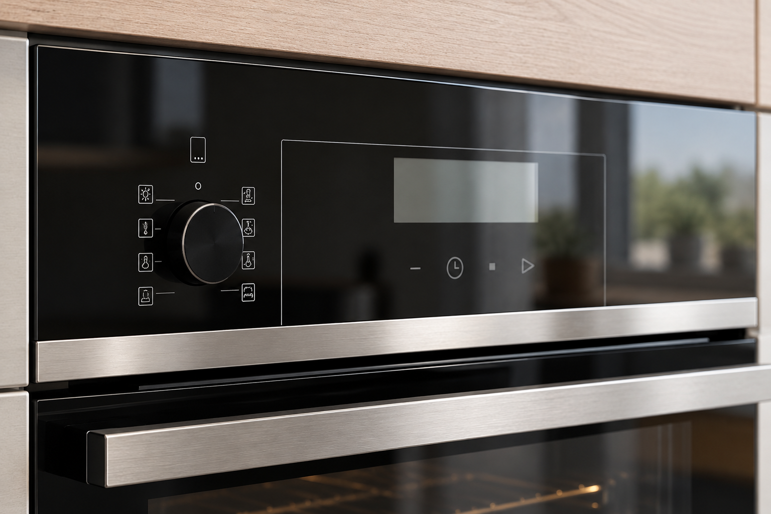
Loose-glass tests can help compare substrates, fabrication conditions, or edge quality under a controlled exposure. Keep geometry and process variables comparable when using those results. A printed and drilled part may not be equivalent to an unprinted rectangular coupon. State which features the screening specimen contains and which it omits. Its outcome answers the screening question only.
Module tests include constraints and interfaces that loose-glass screening cannot reproduce. Evaluate displacement, seal condition, adhesive behavior, display visibility, sensor response, and relevant electrical function through the approved procedure. Engineering supervision and suitable safety controls are necessary where heat, glass breakage, or energized electronics are involved. This article is a planning framework, not an instruction to conduct a hazardous improvised test.
Define acceptance before observing the result
Write separate criteria for cracks, chips, print changes, coating appearance, bond condition, dimensional movement, moisture entry, and module function where these are relevant. Decide how and when each item will be inspected. A panel can remain intact while its display becomes unreadable or its touch response changes. Conversely, a cosmetic observation may need classification rather than an automatic structural-failure label.
Photograph and measure the initial condition. Use the same viewing conditions and functional sequence after exposure. Include an intermediate inspection only if it is part of the planned method and does not disturb the assembly. Define how an inconclusive reading, broken sensor, or interrupted cycle will be handled. Do not change acceptance criteria after seeing the samples merely to obtain a passing result.
Build a test record that supports a decision
| Record | Required information | Decision supported |
|---|---|---|
| Test purpose | Service event, screening or qualification | Whether the chosen exposure answers the question |
| Specimen identity | Material, edges, printing, revision and batch | Whether the evidence represents production |
| Assembly condition | Housing, restraint, adhesive and cure | Whether interfaces and loads are reproduced |
| Temperature history | Sensor locations, actual traces and transitions | Whether the intended exposure occurred |
| Acceptance | Initial observations, agreed criteria and final results | Whether integrity and function remain acceptable |
| Deviations | Interruptions, sensor failures and procedural changes | Whether the result can be used or needs repetition |
The table deliberately contains no temperature or cycle-count recommendation. Those values require application-specific justification. Save raw measurement files, not only a summarized pass sheet.
Investigate a failure without destroying the evidence
Stop and contain the affected samples according to the laboratory procedure. Preserve fragments, assembly positions, adhesive condition, and the most recent temperature history. Photograph the damage before cleaning or disassembly. Note when a crack was first observed; do not assume its exact initiation time from the final image. Retain unfailed samples from the same population for comparison.
Review material identity, edge damage, restraint, sensor placement, test deviation, and component differences before assigning a cause. If a trial changes the mounting arrangement, keep other relevant conditions stable and document the change. A successful repeat with several variables changed cannot establish which variable caused the failure. Have the appropriate specialists examine fracture or material evidence when the conclusion affects safety or product release.
Release the qualification with its boundaries
State the tested configuration, procedure revision, actual exposure, sample population, observed outcomes, unresolved issues, and approval authority. Explain which changes require review, such as a new substrate, altered edge process, different adhesive, revised aperture, or changed housing. Keep qualification evidence linked to the production drawing and purchasing specification.
For a supplier discussion, provide the module drawings and intended thermal duty rather than asking only for heat-resistant glass. Kanger’s appliance-panel product family identifies a possible component category; it does not replace qualification of the finished appliance. Educational descriptions of glass annealing and stress are useful background, but they cannot establish the cycle or acceptance limit for an OEM control module.
Frequently asked questions
Does a loose-glass thermal shock test qualify a complete control module?
No. It can provide material or process screening evidence, but mounting restraint, adhesive, print layers, sensors, and displays introduce additional conditions. Qualification should represent the intended production assembly and its required functions.
Can chamber air temperature be used as the only temperature record?
Only if the validated procedure justifies that approach. When gradients or specimen temperature affect the conclusion, measure the relevant specimen locations and retain the actual histories alongside the chamber program.
What temperature difference should be specified?
There is no universal value in this guide. Use the intended duty, exact material and assembly data, applicable requirements, and a justified laboratory procedure. Avoid transferring a cooktop glass-ceramic limit to a tempered control fascia.
What changes can make an old test unrepresentative?
Changes to material, dimensions, holes, edges, printing, mounting, housing, adhesive, curing, or functional layers may matter. Review the mechanism and scope of the change before deciding whether existing evidence remains applicable.
Related appliance-glass resources
Use the product overview to identify the component family and the engineering guides to define interfaces. These references support a drawing-led supplier discussion; they do not establish universal tolerances or replace validation of the intended appliance assembly.
- Thermal Shock Resisitance Tempared Glass For Household Appliances Panel Product
- Tempered Glass Appliance Panels: OEM Specification Guide
- How to Set Mounting Clearances for Appliance Control Panel Glass Under Thermal Expansion
- Designing the Sealing Interface Around Appliance Control Panel Glass
- How to Specify Durable Screen Printing on Appliance Control Panel Glass
Sources and method references
The linked references explain fabrication sequence, measurement principles or the stated inspection method. Apply their scope carefully: a general glass bulletin or instrument description is not certification of a Kanger part and supplies no project-specific acceptance limit.
- NGA: fabrication before heat treatment; general principle, not an appliance tolerance
- NIST: measurement uncertainty
- NIST: metrological traceability and fitness for purpose
Educational video: Annealing and Tension in Glass
This museum explanation introduces glass stress and thermal history. Annealing and tempering serve different purposes. The demonstration provides material background, not an appliance qualification cycle or a Kanger process claim.

Watch Annealing and Tension in Glass from Corning Museum of Glass


