Kanger Glass-ceramic Co., Ltd.
A glass cutting diamond blade removes material through a saw kerf rather than creating a score for later separation. Whether it is appropriate depends on the glass family, geometry, edge requirement, machine, blade specification, support, and coolant system. Choose a blade through the equipment and tool suppliers’ documented guidance and validate the output on representative material. For appliance panels, the question is how to produce the required finished component before tempering, not how to improvise a cut in a delivered tempered pane. No universal blade speed or feed rate is suitable for every glass.
Decide whether the feature needs a saw cut
Sawing, scoring, drilling, and grinding are different processes. A saw may be proposed where the geometry or material-removal requirement fits that route; a straight rectangular blank may be produced by another controlled method. Ask what problem the saw operation solves and how its output connects to the final drawing. Do not assume a diamond blade is automatically the most accurate or least damaging choice because it can remove material.
Identify whether the cut creates a rough blank, an accessible edge, a slot, or another feature. The feature’s accessibility and support influence what can be proposed. Internal corners and enclosed features may need a different machining route. The quotation should explain the proposed sequence and any finishing allowance. Avoid specifying a blade alone while leaving kerf, edge finish, and final feature geometry unresolved.
Confirm the material and treatment state
Specify the actual substrate, thickness, surface system, and current processing stage. Soda-lime glass, borosilicate, glass-ceramic, and layered products should not be treated as interchangeable because they share the word glass. A blade’s application label must be checked against the intended material and machine. If the supplier proposes a trial on another substrate, ask how that trial will support the production decision.
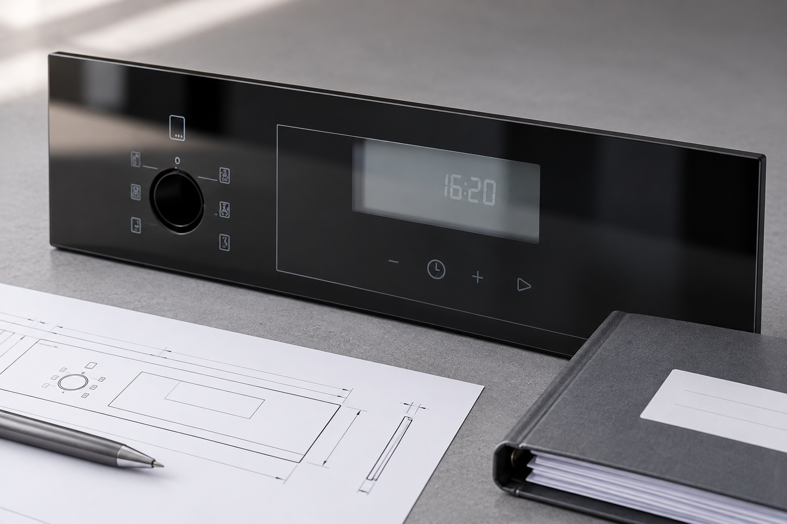
For conventional thermal-tempered flat glass, required fabrication should be planned before heat treatment. NGA advises against post-treatment fabrication because it may weaken or break the pane. A saw blade suitable for an untreated blank is not evidence that a finished tempered panel can be resized safely. When the delivered geometry is wrong, resolve the drawing and remake route rather than treating workshop sawing as routine rework.
Select the blade as part of the machine system
Blade diameter, mounting, speed rating, rim or segment design, kerf, bond, and intended use need to match the machine and application. Follow the manufacturer’s instructions and guards. A blade that fits the spindle is not necessarily compatible with the spindle speed or the glass. Keep the blade’s identity and application documentation in the setup record so replacements do not silently change the process.
Ask the tool supplier what information is needed to recommend a blade: material family, thickness, cut geometry, machine capability, coolant, and desired output. Confirm whether the recommendation concerns rough cutting or a finish that can meet the drawing directly. Avoid selecting from photographs or a generic “stone and glass” description without clarifying the actual application. Any claimed capability should be demonstrated on the relevant output.
Control support and the exit condition
The workholding arrangement should support the part through the intended cut without imposing an unreviewed load. Consider the region that becomes separated and how it remains supported. A cut can appear satisfactory at the entry while the exit edge is damaged when the offcut moves. Define the fixture, locating surfaces, and part orientation before a trial so operators do not invent support positions during production.
Protect viewing surfaces, print, and coatings where the process requires it. Clamps, support pads, and debris can leave marks unrelated to the blade’s cutting performance. Inspect both the cut feature and the surrounding surfaces. If a setup uses a sacrificial support or another process aid, verify its compatibility and replacement condition. The process should identify when damaged or contaminated support materials require a stop.
Use the approved coolant and operating conditions
Where the system uses coolant, follow the machine and blade instructions for material, delivery, maintenance, and safe operation. Keep coolant flow and condition within the approved process. Do not operate a blade dry merely because one small sample survived, and do not invent a wet process for equipment that was not designed for it. The actual machine documentation governs the operating conditions.
Record the setup used to establish the cut, including blade identity, machine, material, support, and approved operating variables. Numerical settings should come from the controlled trial and equipment limits. A speed copied from a stone-cutting example is not a validated glass setting. If the trial requires adjustments, record the sequence and inspect the result so the selected condition can be reproduced rather than remembered by one operator.
Account for kerf and finishing allowance
The blade removes a finite width of material. The process plan needs to define how the cutting path, blade condition, and required allowance relate to the finished dimension. Do not center a path on a final drawing line without reviewing which side of the kerf produces the part. A visually straight cut can still leave the component too small for later grinding or outside its final size requirement.
Specify whether the sawn edge remains on the finished component or is subsequently ground and polished. Identify the final profile, corner transitions, and inspection method. Keep rough-stage measurements distinct from finished-stage acceptance. If blade wear or a changed kerf affects size, the process needs a defined compensation or replacement rule supported by measurements. A generic blade nominal width does not replace inspection of the actual output.
Diamond-saw qualification checklist
| Item | What to establish before production | Evidence on the produced part |
|---|---|---|
| Substrate | Material family, thickness, surface system, and treatment stage | Trial represents the actual intended component |
| Blade compatibility | Mounting, rating, intended material, and approved machine use | No unreviewed substitution in the production setup |
| Workholding | Locating surfaces, support through the cut, and offcut control | No unsupported exit damage or clamp marks |
| Coolant and operation | Conditions permitted by the equipment and blade documentation | Repeatable cut with recorded settings and process condition |
| Kerf and allowance | Path definition and material reserved for final finishing | Rough geometry supports the required finished size |
| Edge finish | Whether the saw edge is retained or further processed | Final edge profile and condition match the drawing |
| Inspection | Defined points, instruments, units, and surface checks | Dimensions, transitions, and viewing surfaces are acceptable |
This checklist contains no universal blade selection or operating recipe. The numerical process window requires the actual system documentation and validation.
Inspect damage and dimensions as separate outputs
Check the cut location, shape, size, edge condition, and surrounding surface. A dimension within tolerance does not automatically make a chipped edge acceptable. A visually smooth edge does not establish the correct geometry. Define the relevant defect criteria and measurement locations so the supplier and buyer can discuss both outputs clearly. Include the finished component after downstream processing where those stages affect acceptance.
Use a suitable measurement method for the feature. Instrument resolution, alignment, datum selection, and repeatability can influence the result; NIST’s uncertainty guidance gives general context for evaluating measurements. The drawing should still provide the tolerance and decision rule. If a trial result lies near a boundary, improve or review the method instead of simply rounding it into acceptance.
Troubleshoot from the first point of failure
If edge damage appears mainly at exit, inspect support and offcut behavior as well as blade and operating conditions. If dimensions drift across a run, compare blade condition, path definition, setup, and measurement repeatability. If scratches appear away from the cut, investigate handling, table covering, debris, and clamps. Different symptoms call for different evidence rather than the same response of changing the blade.
Retain acceptable and affected examples from known setups where practical. Change a defined variable, inspect the result, and record both successful and unsuccessful trials. The goal is a repeatable route for the feature, not a one-off demonstration that material can be removed. Once the route is approved, define the maintenance and reaction instructions needed to keep it under control during production.
Keep the supplier inquiry focused on the finished appliance part
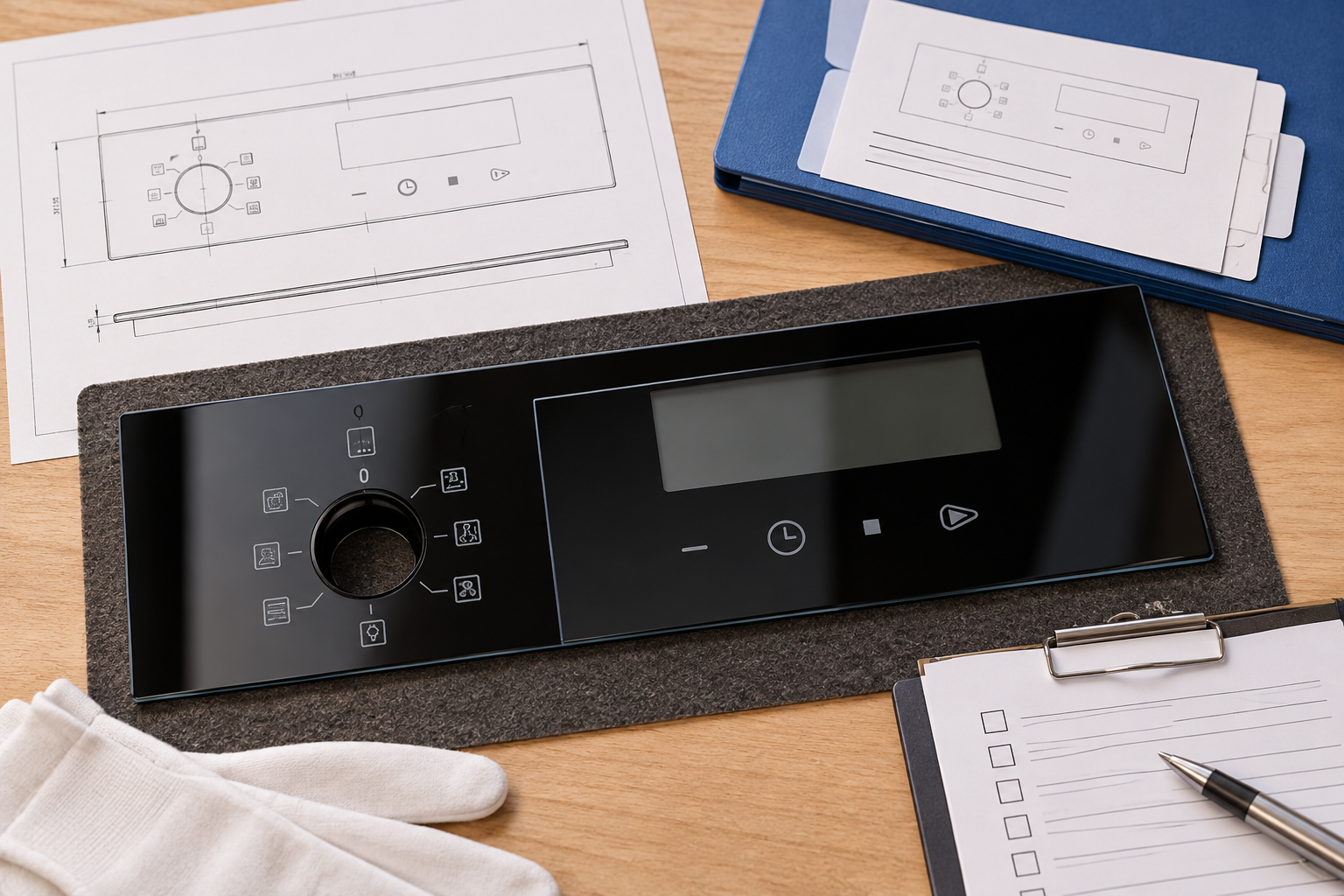
Send the substrate, treatment, final geometry, edge profile, surface orientation, print or coating, and assembly requirements. Explain the feature that needs fabrication and ask the supplier to propose and verify a route. Kanger’s appliance-control glass provides a relevant finished-product context; its product page does not prove that any particular diamond saw is installed or that every requested cut is available.
Confirm feasibility, inspection evidence, and any qualification requirement through the actual quotation. If a design feature changes, review the process route and first article again where necessary. A clear output specification allows the supplier to choose an appropriate controlled method while giving the buyer a concrete basis for acceptance. The blade remains a process input, not a substitute for the component drawing.
Frequently asked questions
Is sawing the same as scoring glass?
No. A saw removes material through a kerf, while scoring prepares a line for separation. Their output and process controls differ, so choose the route for the feature and substrate.
Can a diamond blade resize conventional tempered glass?
Do not plan routine post-tempering resizing. Resolve fabrication before heat treatment and review replacement or remanufacture when the finished geometry is incorrect.
Which blade speed should an OEM specify?
Use the machine and blade limits and a validated process for the actual material. This guide does not supply a universal speed or feed value for glass.
What should be checked after a trial cut?
Check geometry, size, edge damage, surface marks, finishing allowance, and the finished output after downstream operations. A successful separation alone does not release the part.
Related appliance-glass resources
- Thermal Shock Resisitance Tempared Glass For Household Appliances Panel Product
- Tempered Glass Appliance Panels: OEM Specification Guide
- Can Tempered Glass Be Cut? Limits, Risks, and Safer Alternatives
- How to Set Mounting Clearances for Appliance Control Panel Glass Under Thermal Expansion
Sources and further reading
- NGA — fabrication before heat treatment
- NIST — measurement uncertainty
- GGF Glazing Manual — architectural-glass context, not an appliance specification
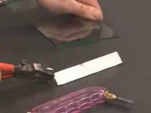
Educational video: Cutting Glass
A museum demonstration of glass cutting introduces scoring and controlled separation. It is educational context, not a machine operating procedure.