 Kanger Glass-ceramic Co., Ltd.
Induction cooker glass mounting clearance design must allow the glass, frame, supports, seals, adhesive, and internal hardware to move through manufacturing tolerances and operating temperatures without hard contact or loss of sealing. The correct gap is not a universal number. It comes from panel size, material data, temperature range, frame expansion, assembly offsets, gasket behavior, adhesive thickness, corner geometry, impact allowance, and appliance validation. A drawing should identify the functional interfaces and state how the clearances are measured in both free and assembled conditions.
This guide turns the intent behind induction cooker glass mounting clearance design into a drawing-led OEM workflow. It does not invent a universal limit, material property, certification, or guarantee. Released requirements, supplier evidence, applicable standards, and representative appliance validation remain controlling.
Map every constrained interface
Identify the perimeter frame, corners, clips, adhesive beads, gasket lands, supports, heater carrier, sensor, display, and any trim. Mark which interfaces locate the panel and which must permit movement. A nominal perimeter gap can be misleading if one corner, clip, screw boss, or distorted frame becomes the real hard stop. Review the full tolerance path in the assembled coordinate system.
For this decision, record the responsible owner, input source, method, acceptance evidence, and reaction to missing information. Review it with design, quality, manufacturing, purchasing, service, and the glass supplier. Use production-intent parts and tolerance extremes when nominal samples cannot resolve the risk, and keep every result linked to the controlled lot and revision.
Calculate relative movement with approved data
Estimate movement for each material using its approved expansion data, effective length, and verified temperature range, then calculate relative displacement between panel and frame. Include direction, restraint, gradients, and asymmetric heating. Supplier data and appliance measurements are more defensible than a generic coefficient copied from an unrelated product. Treat the calculation as an input to validation, not a substitute for it.
For this decision, record the responsible owner, input source, method, acceptance evidence, and reaction to missing information. Review it with design, quality, manufacturing, purchasing, service, and the glass supplier. Use production-intent parts and tolerance extremes when nominal samples cannot resolve the risk, and keep every result linked to the controlled lot and revision.

Build the dimensional tolerance stack
Combine panel length and width, corner radius, frame opening, position, flatness, support height, gasket, adhesive, clip, and assembly variation using the company-approved stack method. Evaluate worst relevant conditions and statistical capability where justified. Include measurement uncertainty. Check both minimum remaining clearance and maximum visible or sealing gap, because a design can avoid contact yet still fail appearance or ingress requirements.
For this decision, record the responsible owner, input source, method, acceptance evidence, and reaction to missing information. Review it with design, quality, manufacturing, purchasing, service, and the glass supplier. Use production-intent parts and tolerance extremes when nominal samples cannot resolve the risk, and keep every result linked to the controlled lot and revision.
Design corners to avoid hard contact
Corners concentrate the effects of diagonal growth, frame mismatch, assembly shift, and radius variation. Define the panel radius, frame radius, corner relief, edge finish, and locating strategy together. Avoid sharp metal features or uncontrolled welds near the glass. Inspect actual corner profiles rather than relying only on nominal CAD. Validate contact-free movement at tolerance extremes and after frame distortion.
For this decision, record the responsible owner, input source, method, acceptance evidence, and reaction to missing information. Review it with design, quality, manufacturing, purchasing, service, and the glass supplier. Use production-intent parts and tolerance extremes when nominal samples cannot resolve the risk, and keep every result linked to the controlled lot and revision.
Choose compliant supports and retention
Use supports, gaskets, clips, or adhesive systems that maintain location without imposing point loads. Define contact width, hardness or stiffness, compression range, cure state, thickness, and aging conditions as applicable. Retention should handle handling and service loads while permitting required in-plane movement. Never assume a soft-looking material remains compliant after temperature, chemicals, compression set, or production variation.
For this decision, record the responsible owner, input source, method, acceptance evidence, and reaction to missing information. Review it with design, quality, manufacturing, purchasing, service, and the glass supplier. Use production-intent parts and tolerance extremes when nominal samples cannot resolve the risk, and keep every result linked to the controlled lot and revision.
Control the assembly process
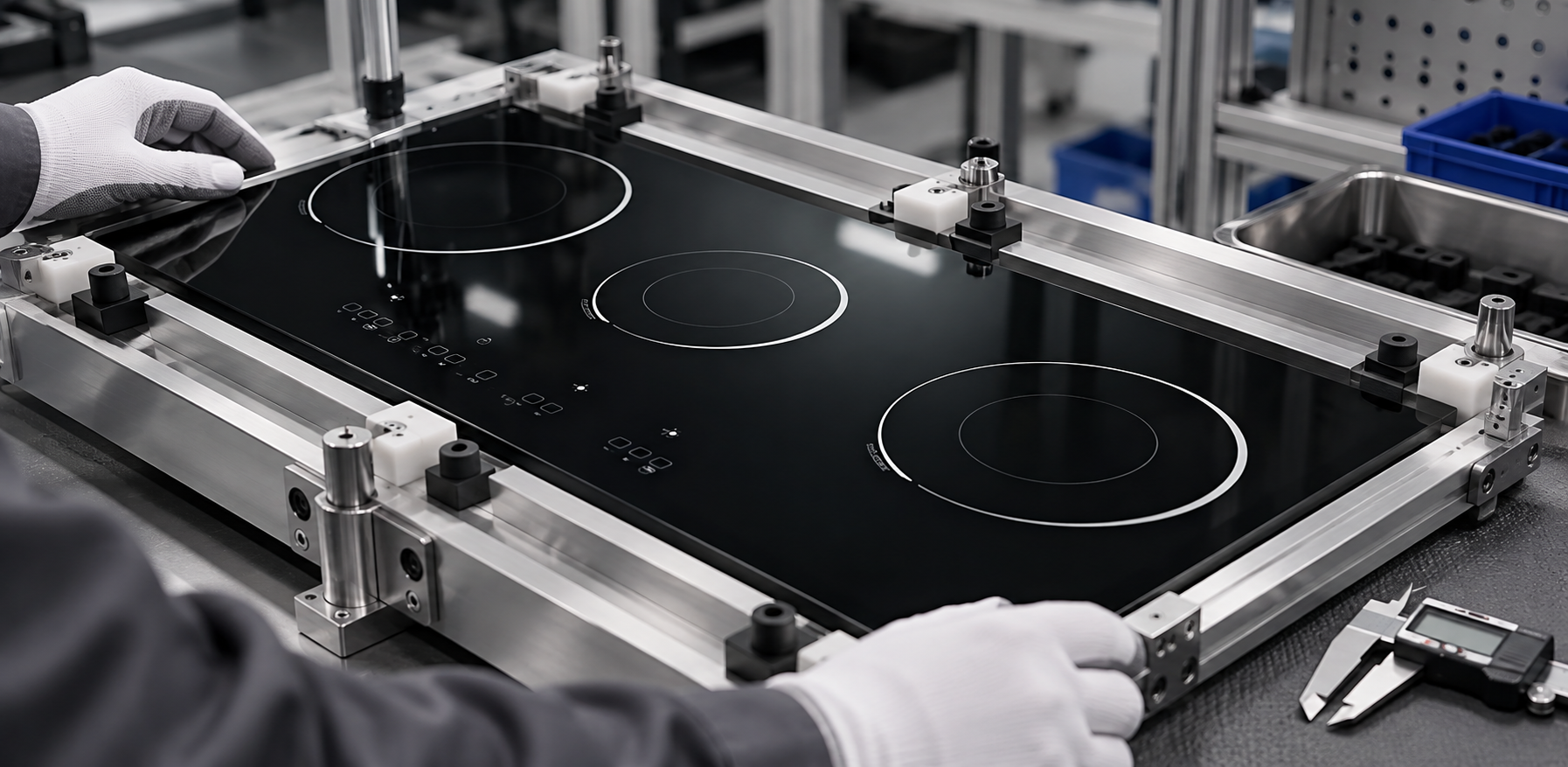
Specify cleaning, placement, fixture datums, centering method, adhesive volume, gasket joint, clip sequence, fastener control, cure, and inspection. A good drawing can still fail if the line pushes the panel to one side or traps debris. Use go/no-go checks or defined measurements at accessible interfaces. Record frame and panel revision, lot, fixture, operator, and measured gaps for first articles.
For this decision, record the responsible owner, input source, method, acceptance evidence, and reaction to missing information. Review it with design, quality, manufacturing, purchasing, service, and the glass supplier. Use production-intent parts and tolerance extremes when nominal samples cannot resolve the risk, and keep every result linked to the controlled lot and revision.
Validate across thermal and mechanical duty
Instrument representative assemblies at the panel, frame, supports, and nearby components. Run relevant heating zones, cookware patterns, cooling, power cycles, transport, impact, and cleaning exposures under approved procedures. Inspect for contact marks, cracks, seal movement, adhesive distress, print change, rocking, and control response. Test size and assembly extremes, not only one centered nominal sample.
For this decision, record the responsible owner, input source, method, acceptance evidence, and reaction to missing information. Review it with design, quality, manufacturing, purchasing, service, and the glass supplier. Use production-intent parts and tolerance extremes when nominal samples cannot resolve the risk, and keep every result linked to the controlled lot and revision.
Release measurable drawing requirements
State datum, measured location, gap direction, corner exclusion or inclusion, free or assembled condition, temperature, fixture, method, and acceptance. Reference the controlled frame, gasket, adhesive, and installation instructions. Link the calculation and validation report to the released revision. Revalidate after material, panel size, edge, graphics, support, frame, heater, seal, adhesive, or supplier changes.
For this decision, record the responsible owner, input source, method, acceptance evidence, and reaction to missing information. Review it with design, quality, manufacturing, purchasing, service, and the glass supplier. Use production-intent parts and tolerance extremes when nominal samples cannot resolve the risk, and keep every result linked to the controlled lot and revision.
Engineering table
| Design input | Minimum evidence | Release output |
|---|---|---|
| Panel and frame | Dimensions, tolerances and approved material data | Relative movement calculation |
| Temperature | Measured range, gradients and duty | Design thermal envelope |
| Supports/seal | Compression, stiffness, aging and geometry | Interface specification |
| Assembly | Offsets, fixture, adhesive and retention | Controlled work instruction |
| Validation | Tolerance extremes and representative cycles | Approved gap and inspection method |
RFQ, first-article, and production control
At RFQ, provide the controlled drawing and CAD or artwork, application, panel dimensions, edge and surface requirements, annual quantity, packaging, and validation conditions. Ask the supplier to identify assumptions, feasibility limits, and deviations in writing. The quotation, production traveler, and inspection instruction should reference the same released package.
Before first-article approval, verify document identity, dimensions, edge condition, surface, graphics, packaging, and the topic-specific evidence in this guide. Assemble samples in production-intent frames, supports, seals, controls, and thermal hardware when those interfaces can influence the result. Record equipment, setup, sample lot, measurements, photographs, exposure, and disposition.
For serial production, translate the release into supplier and receiving checks with named methods, equipment, sample identity, and reaction plans. Trend results by lot, tool, material batch, print screen, package position, and supplier. When nonconformity appears, contain related material, preserve original evidence before rework, compare it with the approved setup, and verify corrective action on later lots.
Educational video
This neutral Corning Museum of Glass video gives useful background on glass processing and stress. It does not replace calculations, drawings, appliance instructions, or qualification.

Related Kanger resources
- Black glass-ceramic product page
- Glass-ceramic material overview
- Glass ceramic cooktop panel mounting clearance design
- Glass ceramic cooktop panel sealing interface design
For a drawing-led quotation, send Kanger the application, controlled files, quantities, validation requirements, and schedule. Technical review can identify missing information without converting this general guidance into an unsupported product guarantee.
Frequently asked questions
Is there one standard mounting gap for every induction cooker?
No. The gap depends on panel and frame dimensions, approved material data, temperature, supports, sealing, assembly variation, and validation.
Should expansion be calculated from maximum temperature only?
No. Relative movement depends on effective length, material properties, gradients, restraint, temperature distribution, and the operating sequence.
Why are corners checked separately?
Diagonal movement, radius mismatch, assembly offset, and frame distortion can make a corner the first hard-contact point.
How should the gap be shown on the drawing?
Define datums, locations, direction, condition, temperature, fixture, measurement method, acceptance, and referenced mating parts.


