 Kanger Glass-ceramic Co., Ltd.
To specify durable screen printing on white ceramic glass, define the visible marks and the printing process separately, then qualify the finished panel after representative heating, cleaning, handling, and assembly. A drawing should locate each zone ring and control symbol; an appearance master should define contrast and acceptable defects; and a test plan should state what constitutes loss of legibility, adhesion, or color consistency. Do not assume that a generic glass-ink claim, a photograph, or a tape result alone proves durability on the intended white cooktop assembly.
The distinctive challenge is that a low-contrast gray mark can look elegant against an opaque white surface in a showroom yet disappear under glare, shift in tone across lots, or become harder to read after cleaning. This article addresses the decoration and verification of a white glass-ceramic panel, not the mechanical specification of its corners or the seal beneath it.
Start with the function of every printed mark
Separate functional markings from appearance-only decoration. A cooking-zone outline, power icon, warning symbol, alignment mark, and decorative border have different consequences if they fade or move. Identify which ones a user must read at a glance, which ones an assembly operator needs, and which ones simply support the visual language of the appliance. The equipment maker, not a general article, must determine any applicable safety-label requirements.
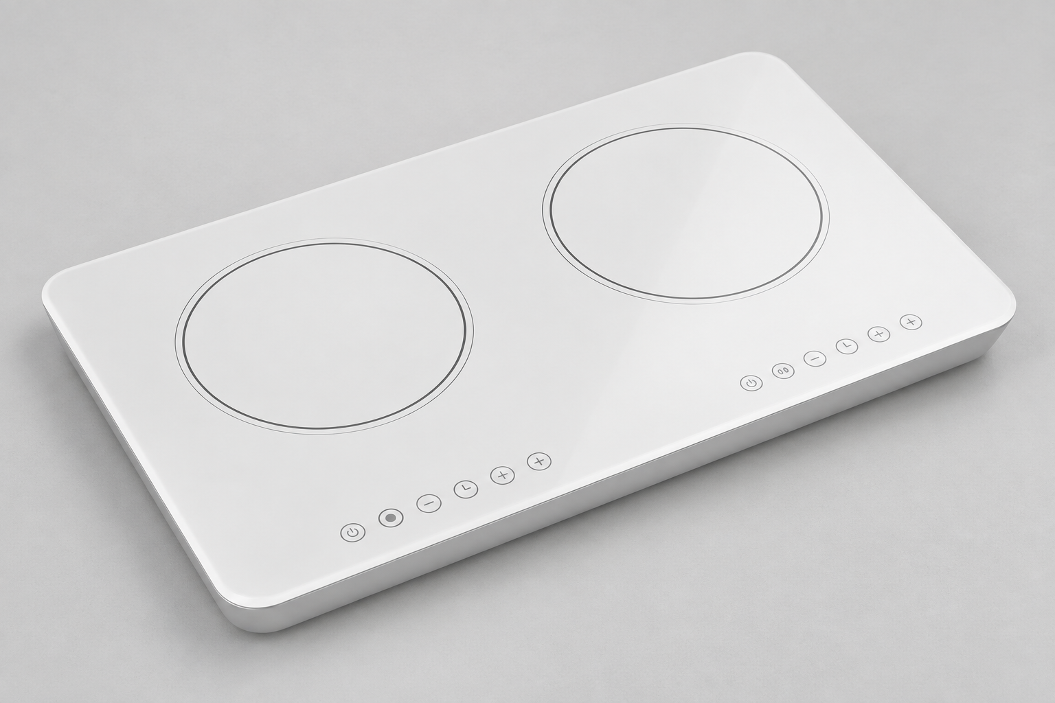
Place each mark on a controlled artwork file tied to the panel drawing revision. Define its location from actual panel datums rather than a loosely positioned marketing rendering. Mark the view side, print side, orientation, centerlines, line widths, and relationship to cutouts, edge finishes, touch sensing, and the heated zones. The printer should receive vector artwork, an approved physical appearance sample, and a list of critical features. A photograph is useful for intent but is not a substitute for measurable geometry.
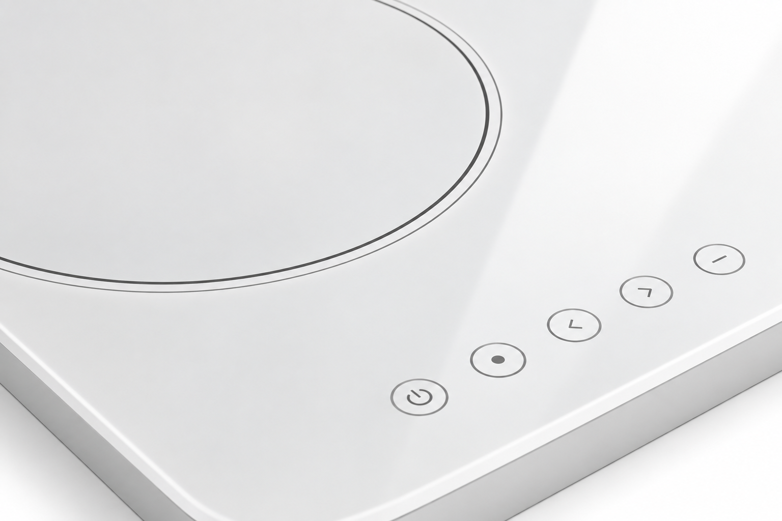
For the white glass-ceramic product family, request a production-intent sample that preserves the actual white surface, cooking-zone graphics, and control area. Product imagery illustrates the visual category; it does not certify a specific ink chemistry, firing schedule, or long-term print performance.
Choose a compatible process, not a generic label
“Screen printed” names an application technique, not a durability grade. Ink formulation, surface preparation, screen mesh, deposited layer, drying, firing or curing, and subsequent operations all affect the final decoration. An ink intended for a different glass chemistry or processing route cannot be accepted merely because it looked good on an initial coupon. Obtain the proposed process window and material compatibility evidence from the actual print supplier, then verify it on the chosen ceramic-glass substrate.
Ask whether marks are on the exposed user-facing side or protected underside, and whether any coating, adhesive, gasket, or sensor interacts with them. An exposed marking faces abrasion, spills, scrapers, and cleaner contact; a buried marking may be shielded from wiping but must still survive the process and remain legible through the substrate. An opaque white panel cannot simply be treated as a transparent back-painted sheet. State the actual construction and viewing direction before approving an ink or test method.
The artwork also needs process allowances. Fine lines, tight icon gaps, and large solid areas respond differently to screen deposition and edge spread. Define an allowable line and registration condition using first-article evidence rather than copying an arbitrary tolerance from an unrelated decorative glass product. If a print approaches a hot zone, a bond line, or a touch-sensor area, include the local duty and any electrical or mechanical constraints in the supplier review.
Make contrast measurable on an opaque white ground
White ceramic glass is not visually neutral: its own hue, gloss, texture, and reflected light change the apparent contrast of gray or colored print. Review the mark under controlled illumination, specified viewing distance and angle, and the final installed orientation. Include the unpowered, powered, and any backlit state where relevant. Avoid approving a shade only from a screen image, because displays and photographs add their own color variation.
For quantitative color comparisons, specify the instrument geometry, illuminant, observer convention, backing or fixture, measurement aperture, and location on both the base panel and the mark. NIST’s overview of CIE color measurement explains why standard illuminants, reflectance measurements, and CIELAB comparisons require a stated method. A single color-difference number is not an application-wide acceptance limit; an OEM should approve its own reference and tolerance through a viewing study. Measure a representative production surface, not a loose paper swatch.
Visual acceptance should address missing segments, pinholes, double edges, bleeding, specks, uneven density, and registration against the zone center. Record which are critical to function and which are cosmetic, and establish the inspection lighting and viewing conditions before supplier and buyer compare lots. A white background can make dark particles conspicuous, while low-contrast icons can be difficult to detect if inspection relies on just one light angle.
Build a durability sequence around real use
Do not reduce durability to one scratch or tape check. Map the actual user and assembly exposures: repeated wiping, stated cleaners, temporary spills, moisture, heat cycling, handling before installation, and contact with approved packaging. Define separate acceptance checks for legibility, color, surface condition, and loss of print. Sequence matters: a mark might survive cleaning on a new sample yet become vulnerable after a thermal cycle or vice versa. Use production-intent prints, cure conditions, and panel geometry in the qualification set.
If a cross-cut or tape method is proposed, first confirm that its scope and execution suit the particular ink layer and substrate. ISO 2409:2020 describes an empirical cross-cut classification for paints and varnishes and explicitly notes that it is not a direct adhesion-strength measurement. It does not, by itself, certify a fired ceramic decoration or the finished cooktop. A method adapted to a particular print should be agreed with the supplier and documented; avoid cutting through a functional production part solely to satisfy a generic checklist.
A sensible qualification record compares pre-test and post-test photographs taken in the same conditions, a legibility assessment of critical icons, and any agreed instrument readings. Include a separately agreed method for cleaning, abrasion, and thermal exposure without inventing a universal cycle count. Test after final manufacturing operations, and repeat the relevant part of the sequence when the print material, surface treatment, cure or firing schedule, or cleaner changes.
Decision table for the drawing and approval package
| Control | What the OEM should define | How to verify on a production-intent sample |
|---|---|---|
| Artwork and position | Controlled vector file, revision, datums, print side, critical icons and line locations | Compare the finished panel to the released drawing using agreed fixtures and the visible appearance master |
| White base and print color | Approved panel lot, mark reference, lighting, angle and whether powered states matter | Compare under stated conditions; record instrument method if numerical color limits are specified |
| Print integrity | Function-critical missing segments versus agreed cosmetic defects | Inspect complete zones and touch symbols before and after the agreed exposure sequence |
| Cleaning and wear | Permitted cleaners, contact material, operation and acceptance rule | Repeat a representative cleaning procedure and reassess legibility, color and loss of print |
| Heat and assembly | Installed heat profile, contact with frame, gasket or electronics, and change triggers | Test a production-intent assembly where interface restraint or local temperature affects the print |
This is a decision framework, not a claimed Kanger material specification. The numerical limits, if needed, must be negotiated from a validated sample and the applicable equipment requirements. In particular, color measurement, tape classification, and visual legibility answer different questions; do not combine them into a single undefined “durability” pass.
Inspect the whole part without confusing print and glass defects
A faint symbol can be caused by thin deposition, poor registration, contrast loss, an underlying surface blemish, or reflected light. Inspect the cleaned panel before drawing a conclusion. Record the location, lot, side, illumination, and pre-test condition. Keep a defect map that distinguishes print discontinuity from a chip, scratch, stain, or inclusion in the white base. This helps determine whether the remedy belongs to artwork, printing, glass fabrication, handling, or the assembly process.
First-article approval should include several areas of the panel rather than a single attractive hero photograph. Review the complete perimeter of each cooking ring, small icons, artwork transitions, and zones near edges. Check whether ink at a finished edge can be affected by a gasket or cleaning flow. If the artwork requires an opaque border or masks a touch sensor, add a cross-functional review with the electronics and appliance teams before the supplier freezes tooling.
In incoming inspection, retain the approved physical master, drawing revision, inspection instructions, and the test report connected to the material and process lots. Repeated failures in one location may indicate a screen, cleaning, or handling issue; random specks across the panel may indicate a different cause. A concession on a cosmetic mark is not automatically acceptable for a safety-critical or user-control symbol.
Questions to send with the RFQ
Provide the supplier with the part drawing, vector artwork, print side, installed orientation, white appearance reference, process restrictions, exposure conditions, and sample quantity. Ask for the proposed ink or decoration system, preparation and curing route, registration capability evidence, critical defect controls, and change-notification procedure. Do not request an unsupported generic statement that the print “lasts forever.” Instead, request results against an agreed protocol and the production-intent construction.
Arrange the first sample review so design, quality, assembly, and sourcing can make one release decision. Photograph the approved marks under documented lighting and keep the physical master protected from wear. Record deviations separately. A change in white base shade, graphic color, surface finish, print supplier, firing process, cleaner, or packaging may invalidate an earlier appearance or durability approval even if the drawing dimensions stay unchanged.
For related work, see the ceramic-glass materials and applications guide, the cooktop color-architecture review, the white-panel corner drawing guide, and the white-panel assembly review. Those pages address material selection, geometry, or assembly; this page is specifically about graphic definition and print durability.
Educational video: why a glass enamel is process-dependent
The Corning Museum of Glass video below demonstrates glass enameling as historical material education. It is not an instruction to apply that process to this cooktop or proof of the durability of any proposed ink; the actual decoration system still requires supplier-specific validation.

Frequently asked questions
Is a tape test enough to prove screen-print durability?
No. A suitably selected tape or cross-cut method can contribute evidence for a particular layer, but it does not reproduce cleaning, heat, visual legibility, and assembly duty. Confirm that the method applies to the actual decoration before using it.
Can an OEM approve the gray print from a digital artwork?
No. The white base, gloss and lighting influence perceived contrast. Approve a physical production-intent sample under stated viewing conditions, with instrumental limits only where an agreed method supports them.
Should every mark have the same acceptance rule?
No. A user-control icon or required warning needs an acceptance rule reflecting its function. A decorative border can have a different cosmetic criterion, provided the distinction is documented before inspection.
What changes require another print qualification?
Review changes to substrate, surface finish, print formulation, artwork, application method, firing or cure, cleaning regime, packaging, or the finished assembly. Repeat tests that the change could affect.


