 Kanger Glass-ceramic Co., Ltd.
For a white ceramic glass cooktop panel, specify each outside corner as controlled geometry rather than asking for “rounded corners.” An OEM drawing should show the corner type, nominal radius or profile, tolerance, transition into the straight edges, edge finish, and an agreed inspection method. The radius cannot be chosen from appearance alone: it must fit the surrounding frame, support pattern, handling route, fabrication process, and visible border. The finished assembly—not a generic material name—determines whether the corner is acceptable. This guide focuses on a white opaque cooktop-style panel and on the information a buyer should put in a drawing and first-article review.
Why a white panel needs a corner-specific drawing
A flat top view can make a corner appear trivial. In the real appliance, the corner may sit beside a metal trim, a molded support, a gasket joint, or a point where an assembler first lowers the panel into place. Those interfaces decide the clearance available and whether an edge can touch a harder neighbor. A corner requirement should therefore connect the outline drawing to at least one relevant section view. The section should identify the viewing side, support surface, contact material, visible edge, and the direction in which the panel is installed or removed.
White ceramic glass makes this review especially visible. The pale surface can expose edge discoloration, a rough transition, or a shadow line at the surrounding trim. A visually smooth corner is still not evidence that its outline, edge condition, and assembly gap are correct. Conversely, a small cosmetic difference in a hidden region should not automatically be treated as the same risk as a chip at a supported corner. Define both functional and appearance acceptance zones before the supplier makes samples.
The Kanger white glass-ceramic product page shows the relevant product family. The white glass-ceramic cooktop panel OEM guide covers the broader specification. This article narrows the decision to corner geometry and its verification. For a finished appliance, the white panel assembly-interface review remains the place to resolve the surrounding support and trim relationship.
Define the actual feature: radius, clipped corner, or edge break
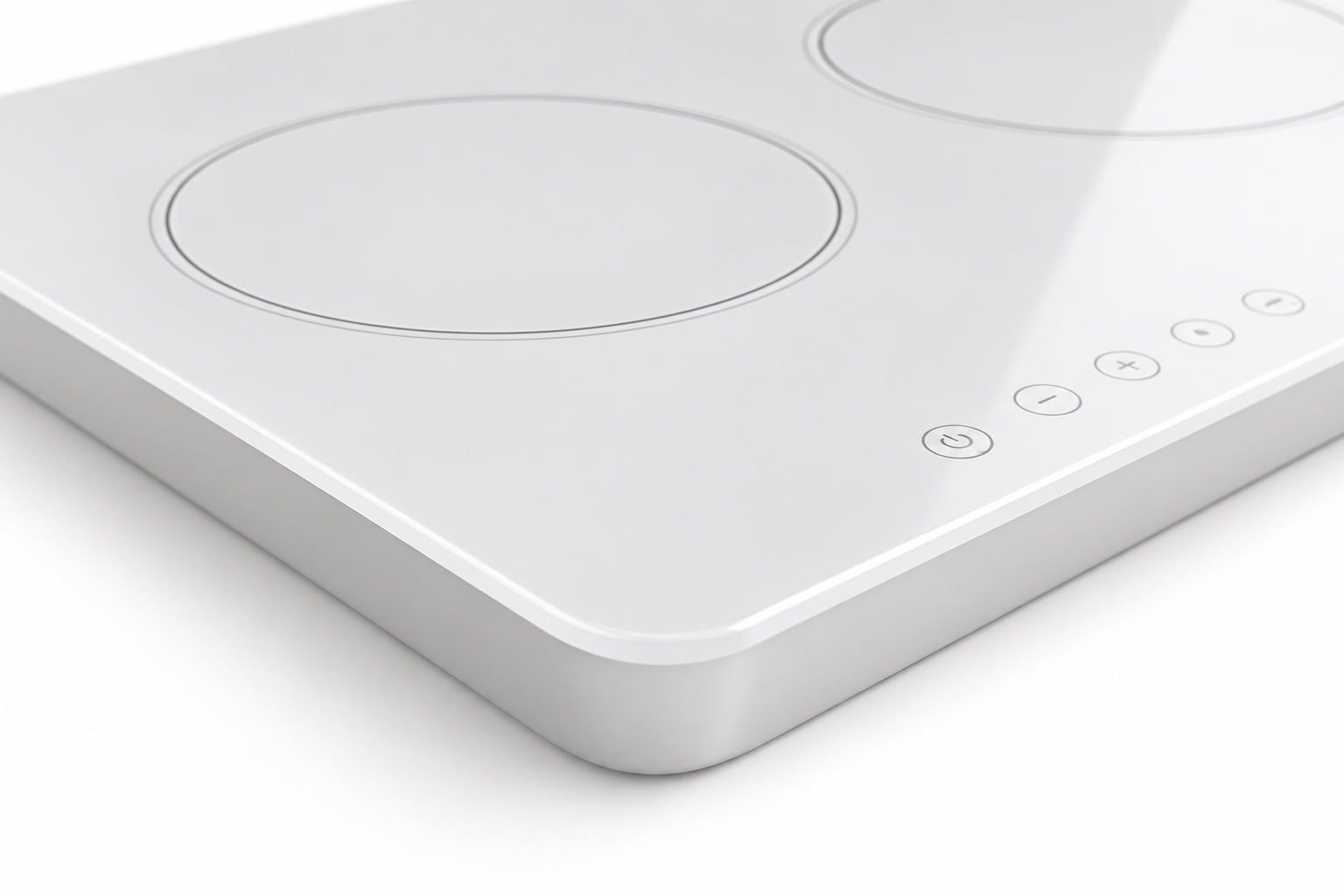
“Rounded” is not a complete geometric instruction. An outside radius is a curved outline joining two straight edges; a clipped corner replaces their intersection with a short straight segment; an edge break changes the sharpness through the thickness without necessarily changing the plan-view outline. These are different finished parts. A drawing should name the intended feature, show it clearly, and state whether all four corners are identical. If one corner is intentionally different for orientation, show that difference explicitly rather than leaving the supplier to infer it from a perspective rendering.
A nominal radius alone also leaves questions. Which surface carries the dimension? Are the straight edges tangent to the arc? Is the radius measured before or after edge finishing? Does a painted, printed, or coated border terminate near the corner? Is the panel measured free-standing, or while seated in a fixture? The answers affect both fabrication and inspection. Use consistent units and a controlled datum system; the NIST guidance on the SI unit of length is a useful reference for unambiguous dimensional notation, but it does not prescribe a radius for this product.
If the corner is visible, provide an approved appearance sample or a photograph under defined lighting, together with a separate dimensional rule. The sample helps communicate surface quality but should never override the drawing. If the corner is hidden inside a frame, retain the dimensional and edge-quality requirements even if the cosmetic acceptance can be simpler.
Select a radius from the assembly and manufacturing route
Start with the available corner envelope in the appliance, then consider the fabrication route and the finished edge. A larger arc is not automatically better if it exposes an unwanted gap or collides with a locating feature. A smaller arc may be difficult to finish consistently or may leave a geometry transition that deserves closer stress and chip review. The correct choice is one the supplier can repeat and the appliance owner can verify in the actual installation.
Ask the manufacturer to review the proposed panel outline and tolerance before releasing tooling or a purchase order. Include panel size, thickness, edge treatment, any coating or print, intended support points, and the frame opening. A corner cannot be judged apart from the edge that leads into it: a tangent break, small notch, chip, or abrupt finish change can matter more than a nominal radius shown in CAD. The NIST practice guide on fractography of ceramics and glasses explains why fracture evidence and origins need careful examination; it should not be read as proof that a particular radius prevents breakage.
Do not borrow a radius or tolerance from another supplier’s material datasheet and treat it as a Kanger product capability. Processing limits depend on the actual material, dimensions, tool path, finishing process, and inspection setup. If a buyer has a preferred value, mark it as a proposal until the supplier confirms manufacturability and the appliance team validates the assembled condition. That distinction prevents an attractive but untested drawing note from becoming an unsupported performance promise.
Control the tangent transition and through-thickness edge
At each outside corner, the arc should meet the straight edges as intended. A visible hook, flat, secondary notch, or unexpected change of curvature can create a poor fit even when a single radius reading is near the nominal value. Specify the permitted profile deviation and inspection method in terms the factory can execute. For a high-visibility edge, pair a profile check with an appearance check under consistent lighting. For an edge that enters a gasket or frame, check the actual contact path as well.
The plan-view radius does not describe the full edge. The top arris, lower arris, and cut surface may receive different finishing operations. The drawing or linked edge-finish specification should state what is required around the corner and where the finish blends into the straight sides. If the white panel includes decoration near the edge, confirm print-side orientation and keep-out distance through the curved region. Avoid a generic note such as “polish all edges” when the accepted finish, measurable defects, and process route remain undefined.
For first articles, inspect the finished component after all cutting, edge finishing, printing, cleaning, and protective-film operations. Earlier process checks are useful, but a corner can be damaged by later handling or packing. Retain photographs of all corners at the same orientation and magnification, and tie them to the part number and drawing revision. If a protective film obscures the edge, define when it is removed and how any resulting marks are distinguished from manufacturing defects.
Measure the corner without creating a new defect
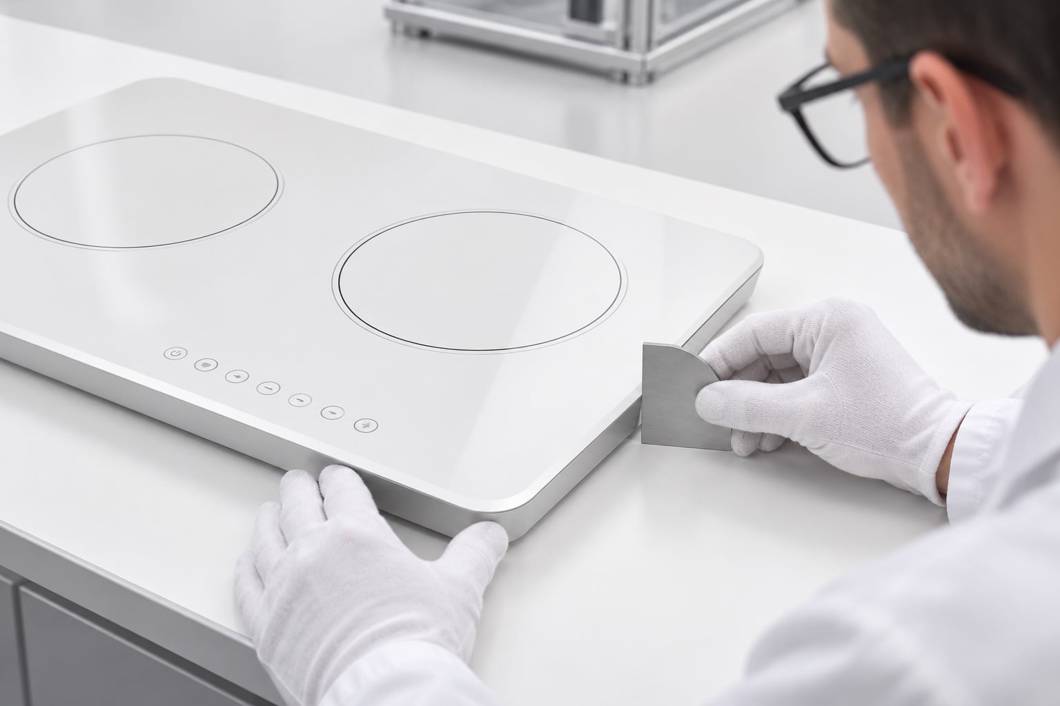
Choose a measurement method that matches the tolerance and production volume. A radius gauge can help with a simple comparison; an optical comparator, calibrated profile system, or coordinate measurement may be appropriate when a fuller contour record is required. The method should state the reference edges, part orientation, support condition, measured surface, reporting resolution, and whether the entire curve or selected points are evaluated. This avoids two inspectors accepting different shapes because each fitted a different segment of the same corner.
Keep hard tools from scraping the white surface or loading a fragile edge. Clean the sample with an approved method and inspect for debris beneath it before seating it on a fixture. If the part is flexible over its span, support it as specified rather than pressing it flat to get a favorable result. Record both the raw observations and the decision rule; a photograph without a scale or an unexplained “OK” mark is weak evidence for a later dispute.
Connect radius acceptance to fit, handling, and first-article approval
A dimensional pass is not the entire approval. Place a production-intent panel in the real or representative frame with the specified gasket, supports, fasteners, and installation sequence. Check every corner for clearance, unintended hard contact, visible gaps, and access for removal. Inspect again after the relevant thermal and handling trials. The project engineer should determine the test duty and acceptance criteria; a supplier blog cannot infer them from the panel color or the word “ceramic.”
The approval package should link drawing revision, sample identification, measured profile, edge-quality observations, fixture setup, assembly result, and any permitted deviation. If a corner is changed after approval, review the effect on print artwork, frame clearance, packaging, assembly tools, and inspection gauges. The NASA Systems Engineering Handbook is a neutral reference for disciplined requirements, verification, and configuration control; it is not an appliance-specific specification.
Buyer’s corner-radius decision table
| Decision point | What the drawing or plan must show | How to verify |
|---|---|---|
| Corner type | Outside radius, clipped corner, or edge break, identified per corner | Compare the finished outline with the released drawing |
| Profile | Nominal geometry, permitted variation, and tangent transition | Use the agreed gauge or recorded contour method |
| Edge condition | Finish on each relevant surface and allowed chip/mark criteria | Inspect after final processing under specified lighting |
| Appearance zone | Which corner surfaces remain visible after assembly | Review an approved sample in the intended viewing condition |
| Frame interface | Corner clearance, support, gasket and installation path | Fit a production-intent part into a representative assembly |
| Change control | Linked drawing, artwork, gauge and effective lot revision | Review the change notice and first-article evidence |
The table is a checklist, not a source of universal dimensions. Enter numerical values only after the OEM and supplier have evidence for this panel and assembly. A target can be practical for one white cooktop design yet inappropriate for another outline, thickness, support arrangement, or manufacturing route.
What to include in a supplier RFQ
Send a controlled 2D drawing and, where useful, a 3D model. Identify the white ceramic-glass material request, panel dimensions, corner profile and tolerance, finished edge, print or coating, viewing and print sides, annual demand, sample quantity, inspection approach, and intended appliance interface. Mark uncertain requirements as open questions. Include a section of the frame and gasket around a representative corner, even if the frame is not supplied by the glass manufacturer. That makes it possible to identify a conflict early rather than after a cosmetic sample has been approved.
Ask the supplier to return specific manufacturability comments: which corner feature is feasible, which operation controls it, what measurement can be repeated at production rate, and where a drawing change is needed. Keep these comments separate from a quotation. A price offered against an incomplete corner definition is not evidence that the supplier accepted a hidden tolerance or fit requirement. For broader panel constraints, read the white cooktop-panel design constraints; for the sample gate, use the OEM glass-ceramic sample approval workflow.
Educational video
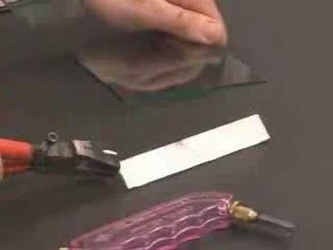
The Corning Museum of Glass video Cutting Glass provides general background on glass-working operations. It does not specify a Kanger panel process or a safe corner dimension for an appliance.
Frequently asked questions
Is one corner radius suitable for every white ceramic glass panel?
No. The available frame envelope, panel geometry, fabrication route, edge finish, visibility, support and service duty can differ. Confirm a radius against the specific drawing and production-intent assembly.
Does a radius gauge alone approve the corner?
No. It can support a profile comparison, but the approved method must also address the complete curve where needed, the tangent transition, finished edge, surface condition, and fit in the surrounding structure.
Should a corner be checked before or after printing and cleaning?
Check the finished first article after all operations that can affect it. In-process measurements may help diagnose variation, but they do not replace inspection of the delivered part.
When should a radius change trigger a new sample review?
Review changes that affect the outline, finishing route, print border, frame clearance, gasket contact, inspection gauge, or handling and packaging. Record which earlier test evidence remains applicable.
References
- NIST: SI Units — Length
- NIST: Fractography of Ceramics and Glasses
- NASA: Systems Engineering Handbook


