 Kanger Glass-ceramic Co., Ltd.
White ceramic glass failure analysis begins by preserving the part and separating four different observations: a true crack, edge chipping, a change in the opaque white surface, and degradation of a printed graphic. Record when each appeared, where it sits relative to the support and heat zones, and the lot and assembly history before cleaning, moving or testing the sample. A fracture pattern can help locate an origin, but a photograph or a material name alone cannot prove whether the cause was processing, handling, assembly restraint, thermal exposure or misuse.
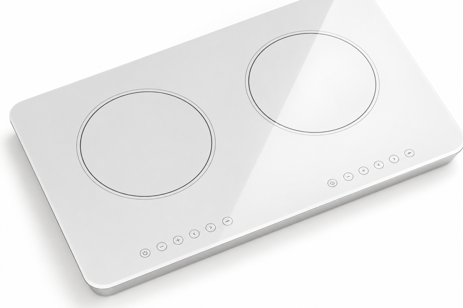
The white panel adds a particular evidence challenge: dark marks, cleaner residue and print changes stand out, yet a reflective surface can also hide fine cracks at one angle. This guide is a triage and evidence plan for an OEM cooktop-panel investigation. It does not claim that the photographed Kanger product has failed; the images are pristine reference-based illustrations, not case-study evidence.
Contain the affected material and preserve the timeline
First make the equipment safe according to the appliance maker’s procedures. Do not operate a cracked or suspect panel to “see if it still works,” and do not use improvised heating tests. Quarantine affected parts and preserve any fragments, gasket, frame, fasteners, packaging and cleaning materials that might explain the event. Assign each item an identifier, photograph it before handling, and note who changed its condition. If the event has a safety consequence, involve the responsible engineering and quality authority immediately.
Collect the part number, drawing revision, substrate and print lot, manufacturing route, dispatch and installation dates, appliance serial and duty history, recorded temperature or fault events, cleaner exposure, and the first person who observed the issue. Ask whether the sample was intact at incoming inspection, after unpacking, after assembly, after a factory heat run, or only after field use. A timeline narrows hypotheses more effectively than a claim that “glass failed in service.”
Compare the suspect with an unused reference from the same lot and a known-good part from a different lot where possible. Store parts separately with protected edges. Avoid wiping the white surface before documenting deposits and print condition; a cleaner can remove or redistribute evidence. The white glass-ceramic product page identifies the relevant application family, but a site image is not a specification or evidence about a particular failed unit.
Map cracks before assigning a cause
Photograph both faces under diffuse and raking light, then trace each crack in a non-contact diagram. Mark the nearest corner, cutout, printed zone, fastener, gasket joint and hot area. Record whether fragments are missing and whether the suspected origin is retained. Fracture surfaces can be easily damaged by touching, cleaning or fitting shards together repeatedly. Keep mating pieces in separate protective bags and let a qualified investigator decide whether microscopy or destructive sampling is necessary.
The NIST fractography guide for ceramics and glasses explains that fracture patterns and the origin can support a cause analysis. It also distinguishes a flaw at an origin from an automatic judgment that a part was manufactured improperly. A crack beginning near an edge is a clue, not proof that the edge-finishing supplier caused it: transport impact, point contact in the frame, thermal gradient or later damage can involve the same region.
When a part has fragmented, do not infer a sequence solely from the longest visible line or from an overview image. A qualified fractographer should reconstruct the event using preserved surfaces, crack direction features, local contact marks and the assembly condition. Record competing explanations and the evidence for and against each. If the origin is lost, say so rather than issuing a confident single-cause verdict.
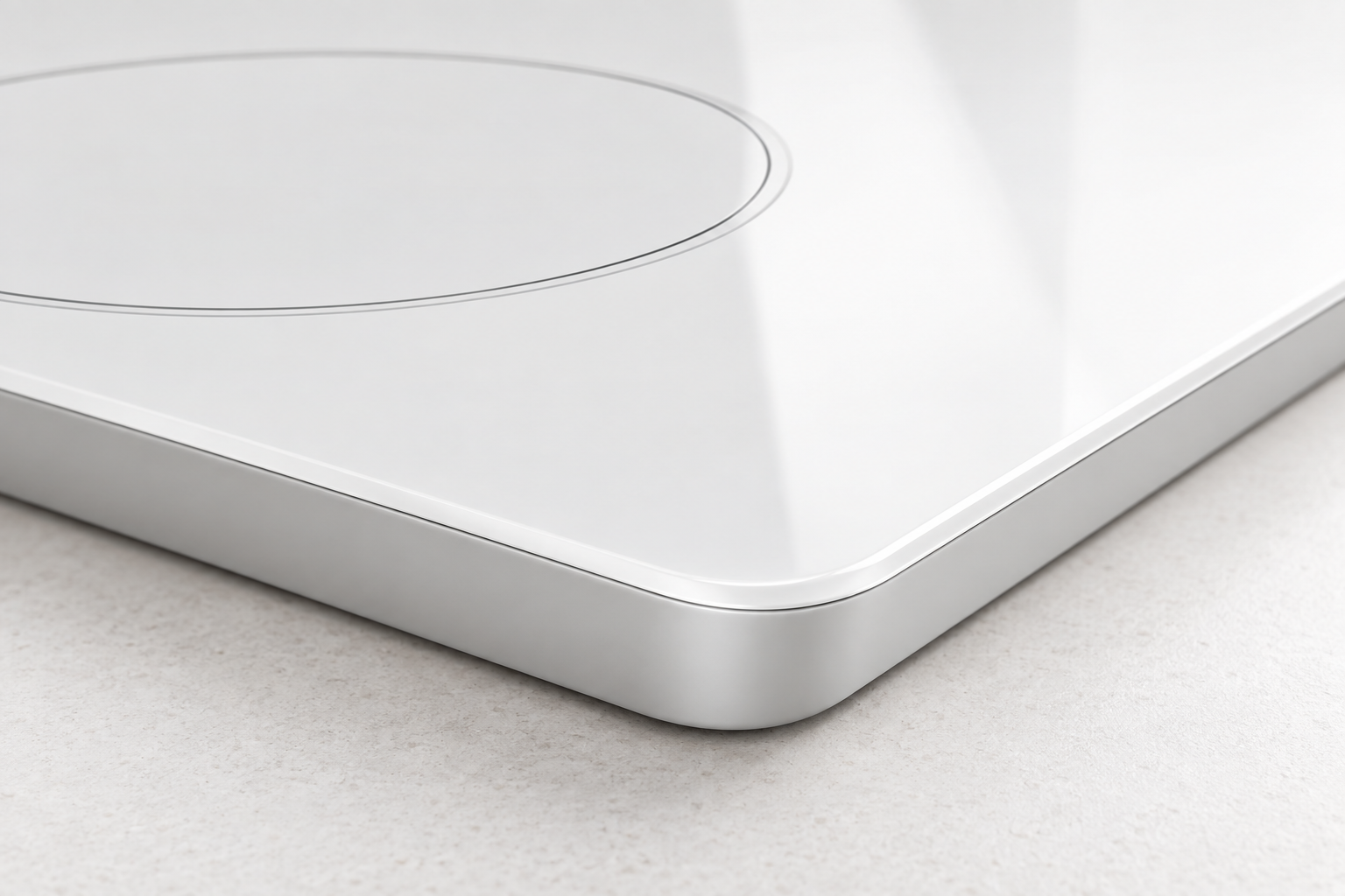
Separate chipping from handling, fit and edge finishing
For a chip, record its location, size according to a project method, exposed face, whether it intersects a print or seal land, and whether secondary cracks radiate from it. Photograph the surrounding frame and packing contact area. A chip discovered at incoming inspection may still have formed in the last operation, packaging or shipment; a post-assembly chip may reflect tool contact, excessive clip force or an insufficient clearance. Investigate the chain rather than assuming the first visible stage is the cause.
Review the released drawing for corner profile, finished-edge callout, support land and gap. The white-panel corner-radius guide addresses geometric definition, whereas this page is about evidence from a failed part. Compare actual dimensions and contact marks with the assembly stack-up. A sharp metal land, trapped particle, or localized support can matter even if the free panel passes a visual inspection.
Do not apply a cosmetic chip concession before confirming whether the defect is in a loaded edge, a heated zone or a user-contact area. The equipment maker must assess consequence and decide if the part is safe, repairable under an approved process, or rejectable. Never grind an edge on a field part as an undocumented remedy.
Investigate discoloration without mislabeling it as glass change
On opaque white ceramic glass, a yellow, gray or brown area could be a removable deposit, cleaner interaction, transfer from cookware or gasket, decoration change, surface damage, or a genuine change in the substrate or coating. The appearance alone does not identify which. Photograph the as-found part under controlled lighting alongside an approved master; map whether the change follows a heated ring, frame line, spill path, icon, or packing contact.
Record the cleaning history and identify the substances by name. After initial evidence capture, a controlled small-area cleaning trial may help distinguish surface residue from persistent change, but only under the approved material-care procedure and with a retained uncleaned control. If the appearance differs from the reference, use the same illumination, viewing angle and instrument method as the white-panel optical inspection method. NIST’s color-measurement overview explains why color comparisons require stated illuminants and geometry. A phone photograph with automatic white balance is useful context, not a reliable color measurement.
Check whether the printed ring or touch icons have changed separately from the white base. Print fading, bleeding or removal may arise from a different material and process than discoloration of the underlying panel. Take a close view that shows the boundary between affected and unaffected areas and, if appropriate, a reference sample of the same print lot. The white-panel print-durability guide covers qualification of those markings rather than fracture analysis.
Use a decision table to keep hypotheses testable
| Observation | Preserve or measure first | Competing explanations to test |
|---|---|---|
| Crack near a supported corner | Fracture surface, edge condition, frame contact and stack-up | Prior edge damage, impact, point load, restraint or thermal gradient |
| Chip at unpacking | Carton position, separator, edge protection, pack photos and shipping timeline | Fabrication, packing contact, transport or unpacking tool |
| Apparent white color shift | As-found appearance, retained control, light method and residue sample | Deposit, cleaner, transfer, coating or substrate change |
| Broken or faded zone graphic | Artwork and print lot, cleaning and heat history, base-surface condition | Ink/process change, abrasion, chemicals or inspection-light effect |
| Fit shift with no visible fracture | Flatness and support measurements in a controlled state | Fixture, frame deformation, packing, measurement setup or panel change |
A table cannot declare the cause. It helps assign an evidence owner and a discriminating test to each hypothesis. Use an agreed reference temperature, datum and measurement orientation. If a part is intact, choose non-destructive examinations first. If laboratory sectioning or fracture is necessary, document the exact question and preserve a control sample.
Design a discriminating test rather than repeating the failure blindly
For suspected thermal loading, obtain the actual appliance heat profile, cool-side temperature, duty cycle, installation constraint, and any abnormal-event history. Do not infer that a material failed a “thermal shock rating” from a single cracked panel. A general glass-container thermal-shock method, for example, is not automatically a cooktop test. A useful comparison tests the production-intent panel in its actual frame and differentiates heat-only from clamp-only, impact-only, and combined exposure where safe and authorized.
For suspected print or surface change, compare a retained lot sample, a cleaned versus uncleaned area, and the same measurement under controlled light. For suspected packing damage, inspect samples from multiple carton positions and reproduce the handling path before changing the part design. Track any test-induced damage so it is not mistaken for the original event. If evidence contradicts the favorite hypothesis, update the cause tree rather than forcing the data to fit a supplier blame narrative.
Keep the scope of qualification explicit. An engineering lab can help distinguish material, interface, and use conditions, but an article cannot set the safety status of an appliance. The OEM retains responsibility for applicable standards, electrical safety, user instructions and any recall or field action decision.
Close the loop with a traceable corrective action
State the confirmed cause, supporting evidence, unresolved uncertainty, affected population and containment disposition. A corrective action may involve edge finish, frame support, gasket, print process, cleaning instruction, packaging or inspection—not necessarily a different ceramic-glass recipe. Validate the change against the failure mode and check for unintended effects. A new gasket, for example, may improve edge contact yet change heat transfer or cleaning access.
Update the drawing, process control, incoming inspection and change notice together. Compare a new production-intent sample with the preserved failure evidence and run the relevant duty sequence. Retain a record linking the new lot and revision to the test result. If the root cause remains uncertain, make that explicit and strengthen containment and monitoring rather than announcing a definitive fix without proof.
The broader ceramic-glass materials guide and the white-panel assembly review provide complementary material and interface context. This page addresses the investigation of a specific observed problem, not initial material selection.
Educational video: stress and fracture in glass
The Corning Museum of Glass demonstration below shows how residual tension can lead to fracture in glass. It is background material science; its historical glass-forming process must not be treated as the process used for this white ceramic-glass panel or as proof of a specific failure cause.

Frequently asked questions
Does a crack near the corner prove a fabrication defect?
No. It identifies an area to investigate. Preserve the fracture surface and examine edge condition, assembly contact, handling and thermal history before concluding the origin or cause.
Can a yellow mark be called permanent discoloration immediately?
No. Record it as found, then use an approved controlled cleaning and comparison method to distinguish residue, transfer, print change and persistent surface change.
Should a failed sample be cleaned before photography?
No. Record the as-found condition first. Cleaning can remove deposits, fragments or transfer evidence and change the interpretation.
Can one failed panel establish a lot-wide root cause?
No. It can generate hypotheses. Compare retained controls, affected and unaffected samples, the process timeline and discriminating tests before judging the affected population.


