 Kanger Glass-ceramic Co., Ltd.
To measure glass thickness, first decide whether you can safely access both faces and whether you need the thickness of one pane or a complete layered assembly. A suitable contact instrument can measure an accessible loose pane; an optical instrument can be useful when direct contact is impractical. Select the method for the material, coating, geometry, and tolerance, then verify it against a reference. For an OEM appliance panel, record measurement locations and the part revision. A nominal catalog thickness or an estimate from a photograph is not a finished-part inspection result.
Define exactly what thickness means on the drawing
A bare glass substrate, a printed glass component, an adhesive-backed panel, and an assembled door stack have different measurable dimensions. If the drawing specifies substrate thickness, a reading taken over print or adhesive may include material outside that requirement. If assembly thickness matters, a bare-glass reading will not answer the question. Give these dimensions separate names and measurement conditions.
Identify the locations to be measured. A chamfered or rounded edge is not the same measurement surface as the full-thickness body. For a curved panel, the orientation of the measuring faces also matters. State whether the requirement applies locally at defined points, to a range across the pane, or to an assembly interface. The inspector should be able to reproduce the measurement without choosing a convenient location that hides variation.
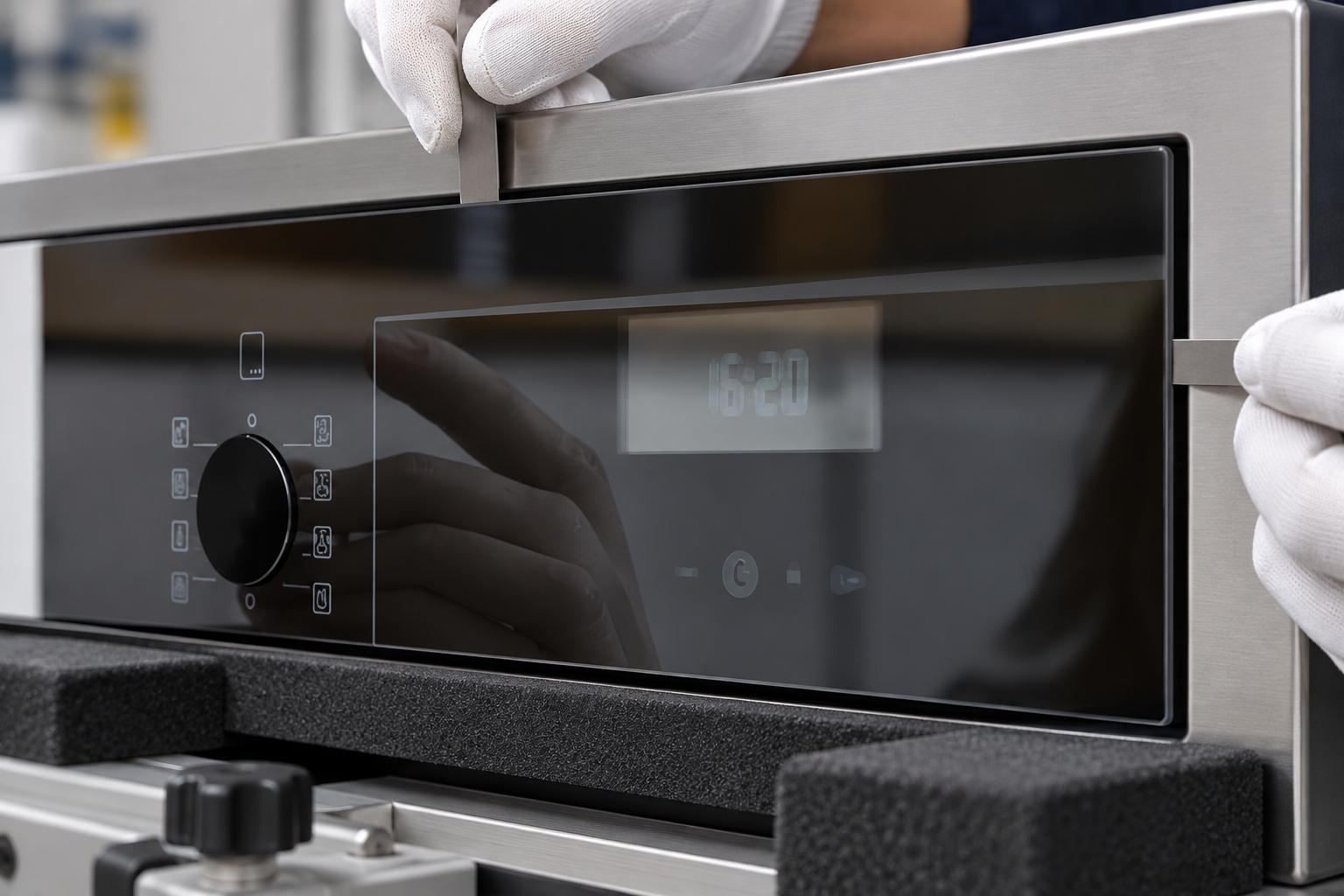
Use a contact method when access and surfaces allow it
A micrometer or another appropriate thickness instrument can be suitable for loose parts with accessible faces. Select the instrument for the expected range, tolerance, surface condition, and contact geometry. Clean the contact surfaces and check the instrument according to the inspection procedure. Use the instrument’s intended force-control method rather than squeezing the glass to obtain a stable-looking number.
Place the measuring faces away from an edge chamfer, chip, print ridge, or coating accumulation unless the drawing specifically includes that feature. Keep the instrument aligned with the local thickness direction. Take repeat readings at the designated points, lifting and reseating the instrument as the procedure requires. Record unusual contact conditions. A caliper reading may be useful for an initial check, but its suitability for final acceptance depends on the tolerance and measurement capability.
Consider optical measurement when contact is impractical
Optical thickness instruments use different principles and are not interchangeable. Some infer distances from reflections at interfaces; others use triangulation or other optical arrangements. The instrument documentation should identify the supported material types, thickness range, coatings, curvature, and access requirements. A device intended for clear flat panes may not give a valid result on a dark printed appliance fascia.
Confirm which interfaces the instrument is detecting. In a layered assembly, several reflections can correspond to glass surfaces, coatings, air gaps, or adhesive layers. Selecting the wrong reflection can produce a plausible but irrelevant number. Verify the setup on a known reference that represents the actual measurement problem. Do not apply an unexplained correction factor merely to make an optical reading match the nominal thickness on the purchase order.
Measure installed or layered glass cautiously
An installed window or appliance assembly may prevent access to one face. Where measurement is necessary, use a validated method that separates the relevant layers. Disassembly should follow the product’s service procedure and be performed by someone qualified for the appliance. Do not remove seals, retainers, or energized components simply to obtain a thickness reading for an inquiry.
If a direct measurement is unavailable, identify that limitation in the record. A drawing, part marking, supplier certificate, or service document may establish the specified thickness, but that is documentary evidence rather than a new physical reading. Keep those categories separate. A quotation based on an uncertain old part should state which dimensions remain to be confirmed before production, especially when mounting clearances or safety-related assemblies depend on them.

Check instrument resolution, repeatability, and uncertainty
The number of digits on a display does not establish the reliability of the result. Consider calibration, contact force, alignment, surface condition, instrument resolution, operator technique, and part variation. NIST’s measurement-uncertainty guidance provides a general framework for reporting and evaluating measurement results. It does not select an acceptable tolerance for a particular glass panel.
Repeatability checks can reveal whether the method is stable enough for the intended decision. Ask more than one inspector to measure the same identified points using the same procedure when operator influence is a concern. Compare the spread with the part tolerance and the agreed decision rule. If a result lies near an acceptance boundary, report the measurement capability rather than rounding the number into compliance. Escalate an unsuitable method before rejecting or releasing production.
Use a location map and a clear inspection record
Draw a simple location map referenced to a repeatable datum. For a rectangular panel, that might identify several body locations while excluding chamfered edges and printed zones. The exact number and position should reflect the drawing and inspection plan, not a universal rule. Record panel orientation, material condition, instrument identity, date, and inspector with the readings.
Store individual results when variation across the pane matters. An average can conceal a local measurement outside the requirement. If a summary is used, preserve the underlying readings and state how it was calculated. Keep units consistent. Avoid mixing an inch-based drawing, a millimeter instrument setting, and a spreadsheet that silently interprets all numbers as the same unit. Conversion should be deliberate and visible in the record.
Method-selection checklist
| Measurement situation | Candidate approach | What must be verified |
|---|---|---|
| Loose flat pane, both faces accessible | Suitable contact thickness instrument | Contact force, alignment, calibration, and exclusion of chamfer or print |
| Printed or coated appliance fascia | Contact at agreed clear points, or a validated optical method | Whether the result includes coating or only the substrate |
| Dark or reflective pane | Method validated on the actual surface system | Instrument response, interface identification, and comparison reference |
| Curved glass | Contact geometry or optical setup suited to local curvature | Measurement direction and repeatability at designated locations |
| Installed single pane | Validated accessible optical method or documentary confirmation | Access limits and distinction between measured and specified thickness |
| Layered door or window stack | Method capable of separating the relevant interfaces | Pane thickness versus adhesive, air gap, and total assembly thickness |
| Result near a tolerance boundary | Approved decision rule using known measurement capability | Uncertainty, repeatability, rounding, and escalation responsibility |
This table selects questions to resolve. It does not claim that one instrument type works for every glass or prescribe a universal resolution-to-tolerance ratio.
A practical OEM example
Suppose a supplier and buyer disagree about the thickness of a printed control panel. The buyer has measured over the printed border; the supplier has measured a clear body location. Before concluding that the lot is nonconforming, both teams should confirm the drawing’s definition and repeat measurements at agreed points using the same surface condition. If the requirement concerns the substrate, the printed border is an unsuitable point unless the method accounts for it.
The next step is to compare instruments and technique on an identified sample. If the disagreement persists, use a method capable of resolving the specified dimension and report its uncertainty. The outcome might be a corrected inspection procedure, a drawing clarification, or a genuine dimensional issue. This example shows how to resolve a measurement disagreement; it is not a Kanger production result or a claim about any panel’s actual thickness.
Turn the measurement into an actionable quotation input
For a custom appliance panel, send the nominal thickness, tolerance, substrate, coating or print state, finished dimensions, and measurement map. Describe how thickness affects the mating bezel, gasket, adhesive, sensor stack, or display. If you only have a measured sample without a released drawing, label the readings as sample observations and ask what additional verification is needed.
Kanger’s appliance-glass product page provides a relevant business connection, but the finished specification belongs to the particular part. A complete inquiry helps the supplier evaluate the requested geometry and finish without assuming a standard thickness or capability. Keep the final agreed thickness and inspection method in the drawing or control plan so later replacement orders do not depend on an old email or an unverified sample.
Frequently asked questions
Can a caliper measure glass thickness?
It can provide a reading when both faces are accessible, but suitability for acceptance depends on the tolerance, contact conditions, calibration, and repeatability. Use the instrument specified by the approved inspection method.
Can I measure thickness through a printed area?
The reading may include print or coating. Use the drawing’s definition and designated points. Do not compare a finished-stack reading with a bare-substrate requirement without accounting for the difference.
Does an optical gauge work on every pane?
No. Material, darkness, coatings, curvature, and multiple interfaces can affect the method. Confirm the instrument’s supported conditions and validate it on a representative reference.
Should I report only the average thickness?
Report the information needed by the requirement. If local variation matters, preserve individual readings and their locations. An average alone can hide a location that needs investigation.
Related appliance-glass resources
- Thermal Shock Resisitance Tempared Glass For Household Appliances Panel Product
- Tempered Glass Appliance Panels: OEM Specification Guide
- How to Set Mounting Clearances for Appliance Control Panel Glass Under Thermal Expansion
- Tempered Glass Appliance Panels: OEM Specification Guide
Sources and further reading
- NIST — measurement uncertainty
- NGA — fabrication before heat treatment
- GGF Glazing Manual — architectural-glass context, not an appliance specification
Educational video: Engineering Drawing Tutorial – NASA’s BEST Students
An educational introduction to communicating geometry through drawings. Apply the dimensional definitions and inspection method agreed for the actual glass part.
Watch Engineering Drawing Tutorial – NASA’s BEST Students from NASA BEST Students


