Kanger Glass-ceramic Co., Ltd.
Backlit glass panels for appliance controls need to be specified as part of an optical and functional assembly. The glass, print or coating, light source, diffuser, display, air gap, bezel, and control electronics can all affect what the user sees. Define each illuminated zone, its appearance in the intended operating states, and its alignment with the module. A loose printed sample cannot establish complete-module light uniformity or readability. For an OEM order, approve representative assembled samples and keep the artwork, surface orientation, and inspection conditions tied to the released part revision.
Separate illuminated zones from opaque masks
Identify display windows, backlit legends, touch symbols, indicator apertures, perimeter masks, and no-print regions. These zones can have different functions. A border intended to hide the module is not the same feature as a legend intended to transmit light. Show the zones on controlled artwork and reference them to the glass geometry and assembly datums.
Define the print or coating face and viewing direction. Reversing the glass or artwork can change the appearance and alignment even if the outside dimensions remain correct. Include the module relationship in the drawing package so the processor does not infer a functional window from a product photograph. If the same panel serves several appliance variants, identify which artwork and lighting configuration belongs to each version.
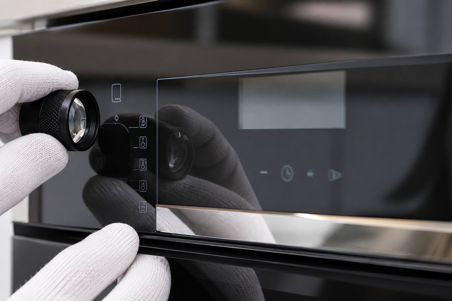
Define appearance in each relevant operating state
An illuminated symbol can look different when the appliance is off, at normal brightness, at a lower setting, or under a different ambient light condition. Decide which states matter for the actual product. Describe the expected visibility of unlit legends, opaque regions, active symbols, and display apertures. Avoid an undefined requirement such as “looks good when lit.”
Use consistent viewing conditions for sample approval. Record ambient lighting, orientation, viewing position, module configuration, and source settings. The responsible product team should set the actual acceptance criteria. A photograph taken with automatic exposure can hide brightness differences or exaggerate a pale area, so retain physical or controlled optical comparison where the requirement needs it. State what the photograph demonstrates and what it cannot measure.
Treat light uniformity as a module question
An uneven illuminated zone may relate to the source arrangement, diffuser, spacing, printed mask, local coating, internal reflections, or assembly alignment. Inspect the assembled module and isolate the relevant variables before blaming the glass. A bright spot directly over one source calls for different investigation from a mark that remains in the same location when the lighting arrangement changes.
Compare identified panels on the same controlled module where that is practical, then compare the module with a reference panel. The comparison can help separate panel-related and module-related behavior. Keep the setup stable and record any change. Do not adjust brightness or camera exposure between samples to make them appear equivalent. The objective is to identify which component or interface needs control.
Align artwork with the display and controls
Printed windows and symbols should reference the same datums used to locate the panel relative to the display, sensors, LEDs, or mechanical controls. Define the positional requirements that matter to the user interface. A legend can be correctly positioned on the glass but offset in the appliance if the module and panel use inconsistent locating references.
Review tolerance accumulation across the glass, artwork, bezel, light source, and electronic module. Ask which dimensions each supplier controls and which are set during assembly. Verify the production-intent combination rather than judging only a graphic file. If a fixture is used to inspect artwork alignment, explain how it represents the released datum and keep its relationship to the real module documented.
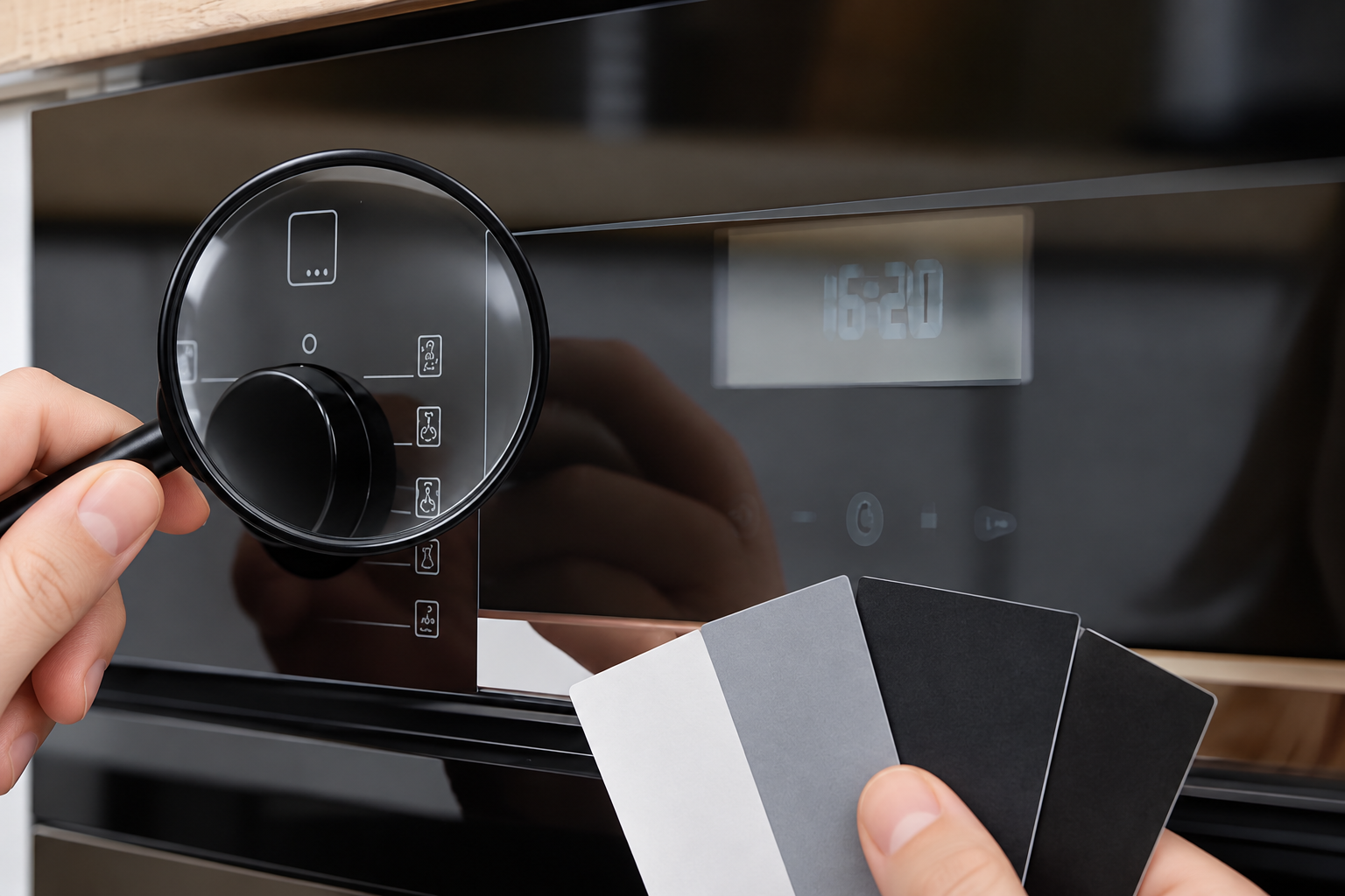
Review print and coating together with transmission
Color, opacity, transmission, pattern definition, and surface appearance can depend on the selected substrate and applied surface system. Specify the intended finished behavior and ask the processor to confirm the proposed materials and route. Do not infer a numerical transmission or an approved finish from a photograph of a dark control panel. The actual part needs a stated requirement and supporting evidence.
An opaque mask and a transmitting zone may need different evaluation methods. If the design uses several print layers or a functional coating, keep the layer order and surface orientation controlled. Sample approval should account for the complete intended stack. A later change to ink, coating, glass source, thickness, or processing can affect the optical result even when the artwork outline is unchanged.
Check touch and display function separately from appearance
If the panel is part of a touch interface, evaluate it with the intended sensing system and assembly. An attractive illuminated sample does not establish touch response, and a functioning touch module does not automatically meet cosmetic requirements. Keep the functional and optical acceptance results separate but linked to the same part and module configuration.
Review the effect of print zones, coatings, adhesive, spacing, and alignment with the responsible module team. Do not claim that a particular glass finish is compatible with every sensing technology. Qualification should cover the real interface and relevant operating conditions. When a symptom appears only after assembly, inspect the full stack rather than replacing the pane repeatedly without checking the module, support, or interface definition.
Backlit-panel specification table
| Requirement | What to define | How to review it |
|---|---|---|
| Zone map | Opaque masks, illuminated legends, display windows, and no-print areas | Controlled artwork linked to the final geometry |
| Orientation | Print or coating face, viewing direction, and assembly datum | Identified sample and assembly section agree |
| Operating states | Off, relevant brightness settings, and intended active symbols | Comparison uses the approved module and source settings |
| Optical appearance | Relevant color, visibility, uniformity, and viewing conditions | Controlled sample or measurement method supports acceptance |
| Registration | Relationship among glass, artwork, bezel, source, and electronics | Tolerance review and production-intent assembly checks |
| Function | Touch response or display operation where applicable | Separate functional evidence for the actual module stack |
| Change control | Substrate, thickness, surface system, artwork, and module revisions | Changes trigger review of affected optical and functional outputs |
This is a qualitative specification table. Numerical transmission, brightness, color, and tolerance values must come from the actual product design and approved inspection plan.
Build a sample approval that can be repeated
Identify the approved panel, artwork, substrate, finish, module, and settings. Keep a reference sample where it is appropriate and record how it is maintained. If an optical measurement is used, describe the method, measurement locations, and instrument conditions. NIST’s uncertainty guidance provides general context for evaluating measurement results; it does not set a brightness or color limit for an appliance interface.
State the scope of approval. A sample may approve the graphic layout without qualifying cleaning durability, thermal exposure, touch behavior, or production variation. Keep those questions in the qualification plan instead of treating one signed photograph as blanket approval. Use production-intent parts for the checks that depend on the final process, and make exceptions or remaining items explicit in the record.
Investigate an uneven legend with a controlled comparison
Imagine that one symbol looks pale at one edge after assembly. First record the lighting and source setting, then compare the panel on an identified reference module if feasible. Check artwork alignment, the transmitting region, diffuser position, source placement, and the bezel relationship. If the pattern follows the panel, investigate its surface system and geometry. If it follows the module, investigate that assembly and its optics.
This example describes an investigation approach, not a Kanger test result or a universal diagnostic rule. Several variables can interact. The team should use evidence from controlled changes to decide what to correct. Avoid masking the symptom by increasing overall brightness until the original acceptance question has been answered; that may alter other display states or user-interface requirements.
Prepare a concrete supplier inquiry
Send Kanger the glass drawing, artwork revision, zone map, intended module, surface orientation, and required optical and functional evidence. Include photographs of the assembled reference with the conditions clearly described. Ask the supplier to confirm the proposed surface system and which requirements need qualification. Kanger’s appliance-control glass page provides relevant product context but does not establish a specific backlit capability or approve an unknown module design.
Keep the final agreed specification in controlled documents. When a module or artwork changes, review affected panel requirements rather than assuming the previous sample approval still applies. A clear handoff connects the finished glass to the user interface and gives both teams a repeatable basis for acceptance. That is more useful than asking for a dark pane with illuminated symbols without defining how it should perform.
Frequently asked questions
Can a loose glass sample prove backlight uniformity?
Not for the complete appliance module. Evaluate the intended glass, source, diffuser, spacing, and assembly together under defined operating and viewing conditions.
Should opaque masks and lit legends use the same criteria?
They serve different functions and may need different evaluation methods. Define the zone map and the intended appearance for each relevant region.
Does good appearance prove touch compatibility?
No. Keep optical approval and functional qualification separate, using the actual sensing system and module stack for the functional check.
What changes should trigger a review?
Review affected requirements when substrate, thickness, print, coating, artwork, adhesive, spacing, source, diffuser, or module geometry changes. Keep approvals tied to identified revisions.
Related appliance-glass resources
- Thermal Shock Resisitance Tempared Glass For Household Appliances Panel Product
- Tempered Glass Appliance Panels: OEM Specification Guide
- How to Specify Durable Screen Printing on Appliance Control Panel Glass
- How to Set Mounting Clearances for Appliance Control Panel Glass Under Thermal Expansion
Sources and further reading
- GGF Glazing Manual — architectural-glass context, not an appliance specification
- NGA — fabrication before heat treatment
- NIST — measurement uncertainty
Educational video: Coloring Objects
A museum explanation of how glass objects receive color provides context for distinguishing substrate appearance from applied decoration. It does not qualify an appliance coating.