Kanger Glass-ceramic Co., Ltd.
Roller wave distortion in glass is a repeating departure from flatness associated with processing glass on rollers in a heat-treatment furnace. It can make reflected straight lines look uneven even when the overall panel dimensions are correct. Buyers should distinguish this local waviness from overall bow, edge lift, mounting distortion, and polarization-dependent anisotropy. A useful specification names the measurement method, panel orientation, inspection region, support conditions, and agreed acceptance criteria. A photograph of a bent reflection is evidence of an appearance concern, but it is not a complete dimensional measurement or a direct assessment of glass strength.
For appliance panels, the practical question is whether the finished part meets the required appearance and assembly performance. Architectural glass methods can provide useful terminology, but a small decorated control fascia may not offer the same measurement area as a large clear pane. Review method suitability before copying a limit into an appliance drawing.
Understand what roller wave includes—and excludes
The National Glass Association’s technical paper on optical distortion measurement distinguishes repeating roll wave from localized edge effects and distortion introduced by assembly. That distinction is important when a customer calls every imperfect reflection “warping.” A single label can hide several different mechanisms and send the investigation toward the wrong process.
Overall bow describes a broader departure from a plane. Edge lift or kink concerns a localized region near an edge. Assembly distortion may change when the support or fastening condition changes. Roller wave concerns a repeating surface profile. These features may coexist, so an inspection record should identify each observed feature rather than forcing all observations into one category.
Do not diagnose the manufacturing route from a decorative product photo. Confirm whether the ordered part is thermally heat-treated, which substrate is used, and which processing conditions are relevant. A glass-ceramic cooktop and a tempered control-panel substrate require their own material and process evidence. The word “glass” is not enough to make all test methods interchangeable.
Why a small wave can create a noticeable reflection
Reflection is sensitive to local surface orientation. A surface can remain close to a nominal plane while changing the direction of reflected light enough to make a straight feature appear uneven. Viewing distance, angle, reflected object, coating, and background all influence the apparent distortion. A complaint should therefore preserve both the panel identity and the scene in which it was noticed.
The relationship between the shape of a wave and its optical effect is more informative than an isolated peak-to-valley value. The ASTM C1651 test-method listing concerns roll-wave optical distortion in heat-treated flat glass. Discuss the appropriate edition and full procedure with the laboratory; a short online description is not a substitute for the complete method.
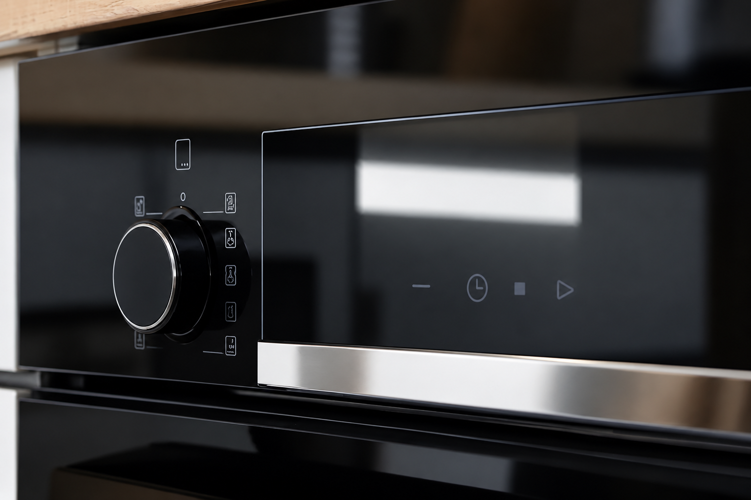
In an appliance, a glossy dark border can emphasize reflected room features, while printing and a display window can interrupt the visible pattern. Inspect the zones that matter to the customer. Do not require an opaque region to behave like an unobstructed transparent window, or assume that an unprinted test coupon represents the finished decorated assembly.
Use a diagnostic table before changing the specification
| Observation | Next check | Record needed |
|---|---|---|
| Repeating reflected-line waviness | Assess local surface profile with a suitable method | Measurement direction, trace location, support and calibration |
| The entire panel appears curved | Assess overall bow independently | Datum plane, free-state condition and panel orientation |
| Only an edge region deviates sharply | Investigate edge lift or a localized form defect | Distance from edge and the region covered by the method |
| Appearance changes after installation | Compare free and assembled conditions | Support locations, gasket condition and assembly procedure |
| Light-dark spots change with filter rotation | Investigate anisotropy separately | Lighting and polarization conditions |
The table separates investigation routes rather than defining pass/fail limits. For the wider dimensional framework, see Kanger’s appliance glass flatness guide. Keep optical appearance, local form, and assembly clearance as related but separately documented requirements.
Choose a measurement method that fits the panel
Before requesting a result, ask whether the instrument can measure the actual part. Relevant constraints include the usable length, decorated surfaces, holes, cutouts, curvature, edge regions, and accessibility. A method that works on an architectural sheet may not provide a meaningful trace across a narrow control fascia. The laboratory should explain any excluded regions and why they are excluded.
Specify the direction of the measurement relative to the expected wave pattern and retain that orientation in the report. Two traces taken in different directions need not describe the same feature. If the production orientation is relevant, ask the supplier to record it rather than reconstructing it later from a photograph.
Identify how the panel is supported and whether it is free of assembly loads. Excessive clamping can alter the shape being measured, while unstable support can make readings difficult to reproduce. Use a documented setup appropriate to the method. Do not invent a generic fixture or contact force and call it a standard test.
The National Glass Association’s distortion-analysis presentation illustrates differences between measurement approaches. Treat it as educational background, not an endorsement of a particular instrument. Request calibration status, measurement uncertainty where relevant, and a clear explanation of how the reported value was obtained.
Write a useful supplier request
A supplier request should include the part drawing, material identification, nominal dimensions, treatment and decoration requirements, and a description of the actual concern. State whether the priority is reflected appearance, assembly fit, or both. Include photographs with the camera position and reflected target described, but avoid asking the supplier to infer a numerical acceptance limit from an image.
Ask for the proposed inspection method before agreeing to a number. The response should identify the measured quantity, units, sampling approach, inspection regions, and reporting format. If the specification uses an optical metric, do not substitute a dimensional metric without explaining the relationship and obtaining agreement.
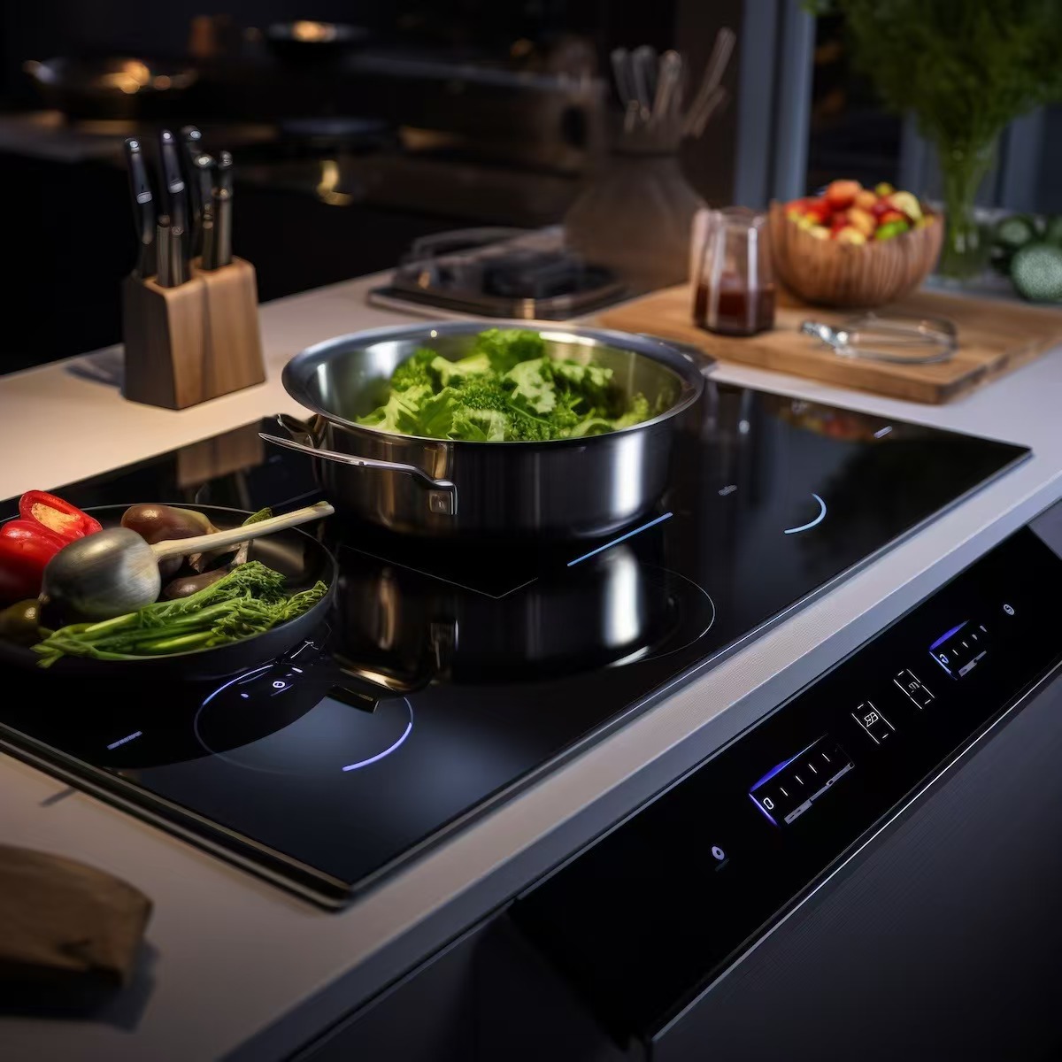
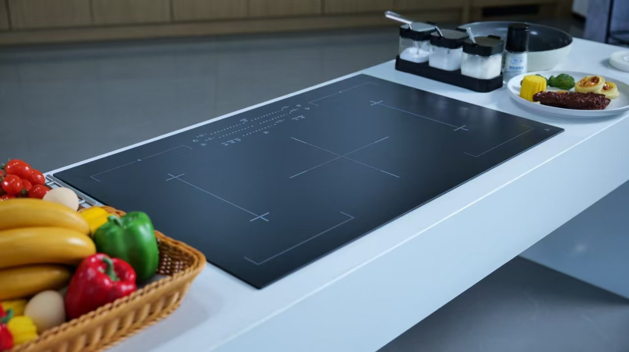
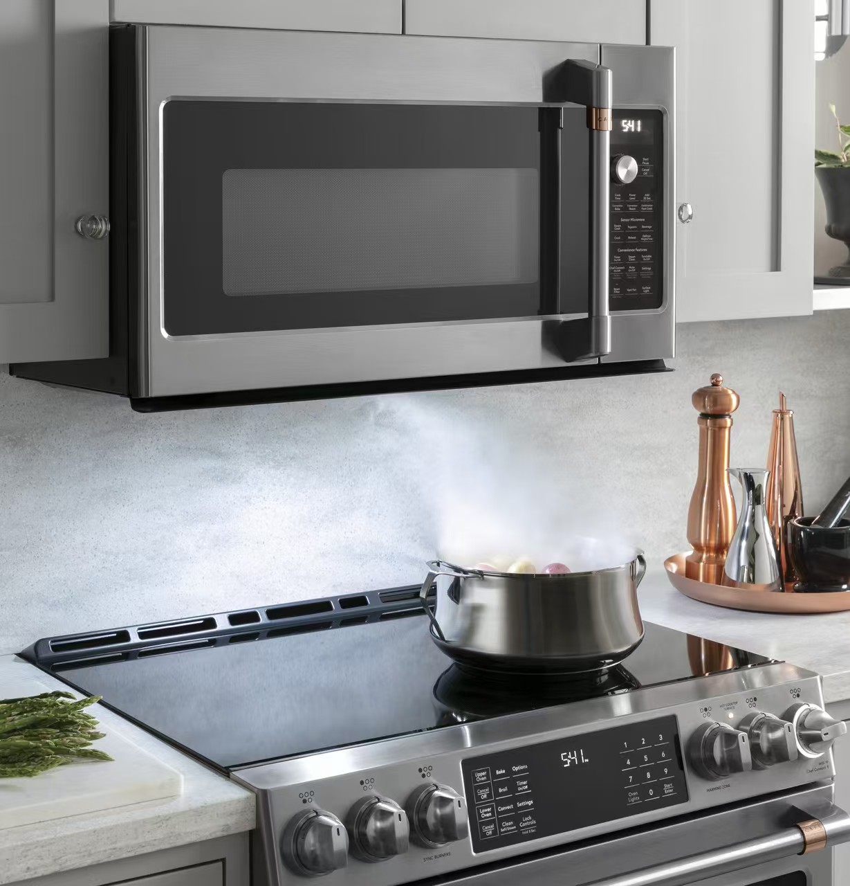
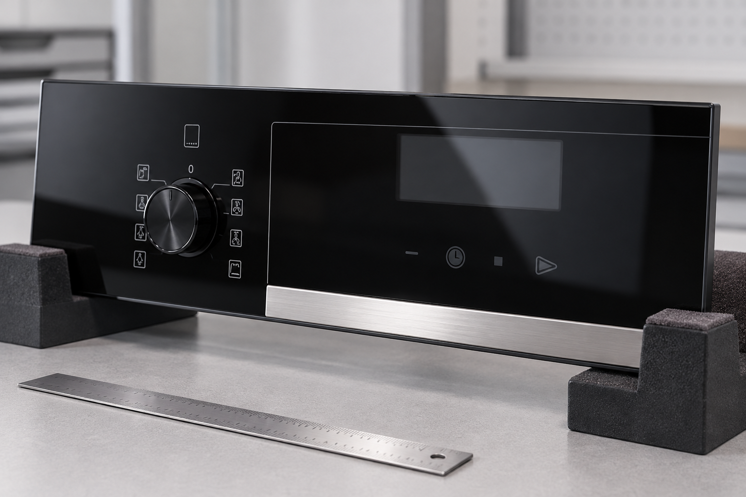
For tempered household-appliance glass panels, connect the appearance request to the finished component. Knob openings, printed masks, display windows, and visible borders can all affect where inspection is meaningful. Product photographs illustrate the component category; they do not establish a guaranteed roller-wave value.
Compare production samples fairly
Use a traceable reference sample and consistent observation conditions. Record the panel side, orientation, lighting, background, and viewing position. Inspect several production-intent samples rather than selecting one unusually favorable piece. Keep lot identities visible throughout the review so variation can be investigated without mixing unrelated evidence.
When comparing suppliers, verify that the reports describe the same quantity and procedure. A report with a smaller number is not necessarily better if its measurement region, support arrangement, or units differ. Request clarification before ranking results. The goal is a comparison that would lead another inspector to the same purchasing decision.
Retain ordinary-use appearance images alongside enhanced diagnostic images. A sharply defined reflection target can make small variations conspicuous, which is useful for troubleshooting. It should not silently replace the viewing conditions agreed for customer acceptance. Both records can be valuable when their purposes are explicit.
Investigate changes after assembly
If a panel passes the agreed incoming review but looks different after assembly, compare its condition before changing the furnace specification. Check whether the support surface, gasket, adhesive, or fasteners introduce a new restraint. Review the assembly procedure with the responsible engineering team rather than loosening parts on an operating appliance.
Keep the service boundary clear: a field user should follow the appliance manufacturer’s instructions and should not disassemble a potentially damaged unit to investigate reflections. Factory engineers can reproduce the concern in a controlled setting with the appropriate precautions. Preserve suspect parts and assembly records before making adjustments that could erase the evidence.
The mounting-clearance guide addresses a complementary question: how the component is located and allowed to move. Correct mounting does not erase a manufacturing form deviation, but it can prevent a separate assembly problem from being mistaken for one.
Close the review with a clear decision
A useful final report identifies the observed feature, the method used, the inspected region, and the acceptance basis. It should state what was not assessed. If additional testing is needed, specify the unanswered question rather than requesting a generic “better quality” certificate. That makes the next action measurable and avoids repeating the same photographs without improving the diagnosis.
Maintain separate evidence for safety, heat-treatment quality, thermal duty, and appearance. A reflection check is not a strength test, and an acceptable dimensional trace does not establish every appliance requirement. Use the OEM specification guide to keep those requirements connected within one purchase package.
Educational presentation
The following Glass Performance Days presentation examines distortion and anisotropy visibility in coated heat-treated glass. Its building-glass examples are background for method selection, not appliance-specific limits or Kanger test results.

Frequently asked questions
Is roller wave the same as overall bow?
No. Roller wave describes repeating local waviness, while overall bow describes a broader departure from a plane. Assess them with appropriate, separately identified methods.
Can a reflection photograph give a roller-wave measurement?
It can document an appearance concern. A numerical result requires a suitable measurement method and recorded conditions; an ordinary photograph alone is not enough.
Does roller wave prove the glass is unsafe?
No direct safety conclusion follows from the appearance alone. Mechanical and appliance safety requirements need their own evidence and qualified assessment.
Can architectural limits be copied onto an appliance drawing?
Only after confirming that the method, part geometry, inspected regions and intended use are suitable. Small decorated panels may require a different agreed assessment.