 Kanger Glass-ceramic Co., Ltd.
Appliance control panel glass corner radius specification should define the outside glass profile, the adjoining straight edges, the edge finish, and the method used to inspect the transition. A radius copied from a bezel drawing is not automatically suitable for the glass. The finished panel must fit the opening without corner contact, preserve the intended seal or adhesive land, and keep printed icons, display windows, and touch zones in their correct positions. Agree the geometry with the glass fabricator before releasing tooling or ordering samples.
This guide concerns a tempered appliance fascia or control cover. A glass-ceramic cooking surface has a different material and process history. Neither a photograph of an attractive corner nor a general building-glass specification establishes the acceptance limits for a particular control module.
Separate the three shapes in the corner
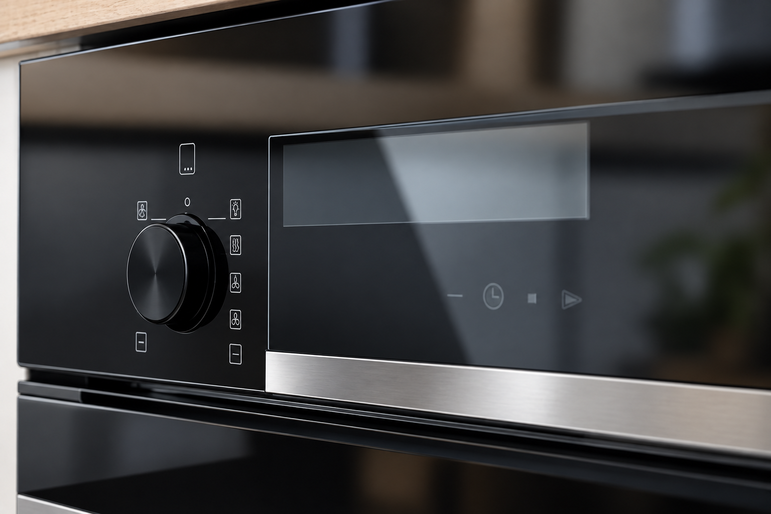
An appliance corner often contains three different profiles: the outline of the glass, the opening in the housing, and the boundary of the visible print mask. Keep them on separate drawing layers. A dark printed border can make the apparent corner look sharper than the actual substrate. Conversely, a bezel can conceal a physically larger glass radius. If inspection follows the visible black line instead of the glass edge, acceptable parts may be rejected and incorrectly cut parts may pass.
Mark the viewing face and the print face. Include an orientation view when the panel is asymmetric or when a rotary-control opening provides an obvious reference. Use a sectional detail to show which face meets a gasket or adhesive. This prevents an inspector from treating an edge bevel, which runs through the thickness, as the plan-view corner radius.
Establish datums before adding dimensions
Choose datums that remain available on the manufactured component. A housing centerline that cannot be located on a loose glass panel is a poor sole reference for incoming inspection. Define the panel coordinate system and explain whether the outline is centered on it or located from two reference edges. Locate display windows and apertures in that same system so their relationship to the corner can be checked.
Specify whether the corner is a constant-radius arc or part of a controlled CAD profile. If it is an arc, identify its tangent relationship with adjoining edges. If styling requires a varying curve, supply the controlled contour rather than forcing an inspector to interpret it as a circle. A radius gauge can check a simple arc qualitatively; it cannot certify an arbitrary spline.
Check the complete fit stack
Compare the maximum possible glass envelope with the minimum possible housing opening. Include corner position, straight-edge dimensions, housing shape, adhesive placement, and the assembly positioning method. An opening can provide generous clearance along the straight edges yet contact the glass at a corner. Check the actual closest approach around the curve instead of subtracting only the nominal overall widths.
Temperature and assembly variation belong in the module review. The glass, metal trim, plastic housing, and adhesive may respond differently. Obtain the properties of the actual materials and validate the design under the application’s conditions. There is no universal corner clearance suitable for every appliance. A drawing should record the selected criterion and the evidence that justified it rather than leave the assembler to force a tight panel into place.
Define edge finish independently
The outside radius and the edge cross-section are separate characteristics. State the agreed arris, bevel, polish, or ground finish where applicable, and identify exceptions around apertures. Avoid terms such as smooth edge without a method or a reference sample. A corner can match its profile yet contain unacceptable chips, sharp remnants, or an inconsistent transition into the straight edge.
For heat-treated glass, agree cutting, drilling, and edge fabrication before heat treatment. The National Glass Association’s fabrication guidance explains why later alteration can disturb the stressed surface. Its architectural context does not provide a ready-made appliance tolerance, but the sequence is relevant. Do not instruct an assembly line to grind a finished tempered corner until it fits. Escalate a mismatch to the drawing and fabrication review.
Protect functional areas near the curve
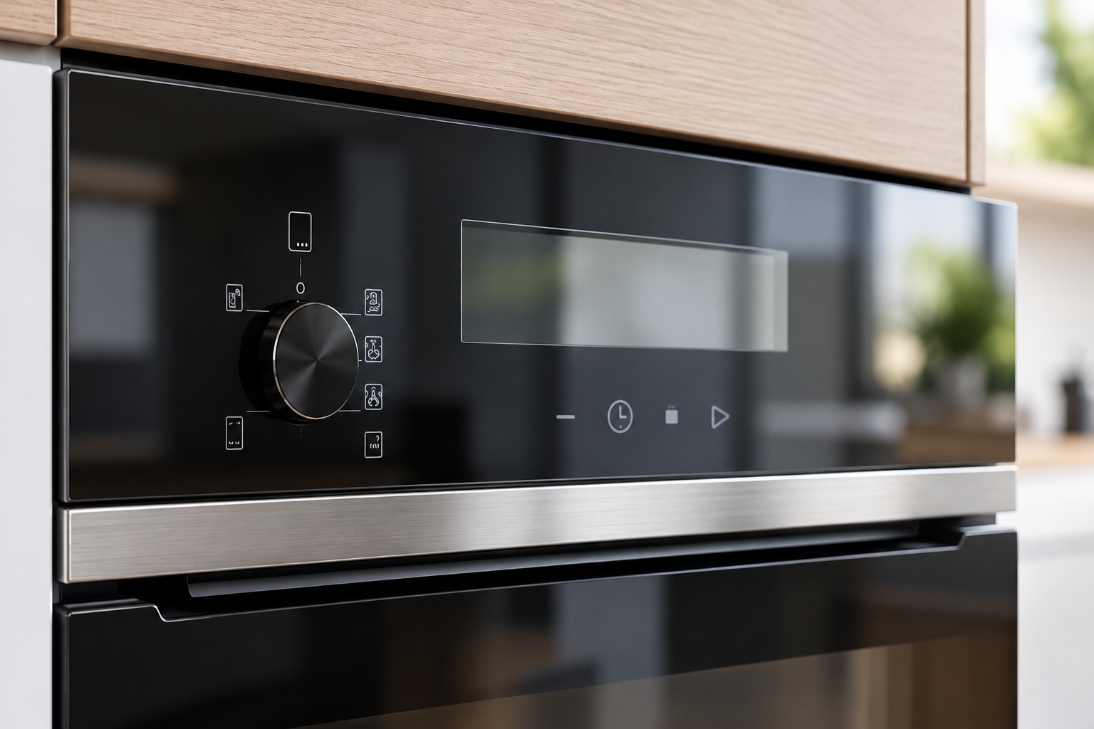
Plot the print mask, transparent display region, sensor region, adhesive land, and gasket path against the actual outline. Look for reduced support or a thin print margin as the corner curves inward. The appearance team may approve a border that creates a difficult manufacturing registration requirement. Resolve that conflict in the drawing rather than accepting each sample according to a different visual judgment.
If artwork appears distorted near the corner, distinguish print registration from outline position. Measure the two independently before assigning the cause. A correctly printed panel with an incorrectly located contour needs a different correction from a correctly shaped panel printed off position. Preserve both results in the inspection record. This distinction is especially useful when a supplier’s glass and printing operations use different setup references.
Agree an inspection method that can reproduce the result
Choose an optical comparator, a suitable coordinate method, or another validated method for the specified profile. Document how the glass is supported, how its edge is detected, which face is measured, and which software alignment is used. Reflections, dark masks, transparent regions, and a bevel can produce different detected boundaries. Ask for the measured contour as well as a single radius value when the boundary is uncertain.
Evaluate repeatability by removing and replacing representative panels. Then compare the supplier’s result with the receiving laboratory’s result on the same parts. NIST’s guidance on uncertainty and traceability supports this approach: an instrument’s displayed precision alone does not establish the uncertainty of the complete measurement. Record the calibration status, setup, operator, and temperature condition appropriate to the agreed method.
Use a corner review sheet
| Review item | Required drawing or record | What the review prevents |
|---|---|---|
| Physical outline | Arc or controlled contour, datums, revision | Inspecting a printed border instead of glass |
| Housing interface | Opening envelope and assembly state | Corner contact hidden by straight-edge clearance |
| Edge cross-section | Finish, face orientation, agreed defect criteria | Confusing a bevel with the outline radius |
| Functional layout | Print mask, display, sensor and adhesive boundaries | A corner change intruding into a functional zone |
| Measurement | Support, boundary detection and alignment method | Different laboratories reporting incompatible results |
This is a specification checklist, not a table of universal dimensions. Fill it with the project’s released criteria and actual sample evidence. A nominal radius without the other records is insufficient for a repeatable acceptance decision.
Validate first articles in the real module
Inspect loose parts first, then assemble representative samples using the intended fixture, adhesive, gasket, and housing. Record whether insertion requires unusual force, whether the panel rocks, and whether a corner becomes a hard contact point. Check that the fixture locates the glass from its intended datums rather than correcting a contour error by shifting the whole part. Perform the module’s functional checks after assembly.
Retain photographs that show the actual glass edge and the mating opening, alongside measured profiles. Include samples near agreed dimensional boundaries where available. A single attractive sample at nominal dimensions does not demonstrate tolerance compatibility. If the design fails, identify whether the remedy belongs in glass geometry, housing geometry, positioning, or the retention system. Record the conclusion before accepting a revised sample.
Control changes and prepare the supplier request
A corner revision can affect cutting programs, grinding tools, housing clearance, print registration, packing supports, and inspection fixtures. Send the revised glass drawing with a marked change view and confirm which files are replaced. Ask the supplier to identify the affected process steps and existing stock. If only the artwork changes, do not silently alter the physical profile; if the physical profile changes, verify related artwork and fixtures.
An effective request includes the material designation, heat-treatment condition, thickness specification, CAD contour, datum scheme, edge finish, functional layout, assembly drawing, inspection method, and intended order quantity. Request manufacturing feedback and first-article evidence for the complete package. Kanger’s appliance-panel product family is a starting point for that discussion; final geometry and performance remain subject to the actual engineering agreement.
Frequently asked questions
Is there one standard corner radius for all appliance control panels?
No. The radius depends on the outline, processing route, mating opening, edge treatment, and functional layout. Obtain fabricator feedback and validate the proposed profile in the intended assembly instead of copying an unrelated product’s value.
Can a printed border be used to measure the glass radius?
Only when the specification explicitly defines a print characteristic. Measure the physical substrate edge separately. The print mask may deliberately have a different curve and may conceal an incorrect glass contour.
Can a finished tempered panel be ground to correct a tight corner?
Do not treat that as routine assembly rework. Fabrication normally precedes heat treatment. Ask the responsible glass engineer and supplier to assess the nonconformity and provide an approved disposition; a replacement may be required.
What should accompany a first-article radius report?
Include the drawing revision, part identity, datum alignment, support arrangement, measurement method, measured contour, edge condition, and module-fit observations. A lone pass stamp or nominal radius does not explain how the corner was accepted.
Related appliance-glass resources
Use the product overview to identify the component family and the engineering guides to define interfaces. These references support a drawing-led supplier discussion; they do not establish universal tolerances or replace validation of the intended appliance assembly.
- Thermal Shock Resisitance Tempared Glass For Household Appliances Panel Product
- Tempered Glass Appliance Panels: OEM Specification Guide
- How to Set Mounting Clearances for Appliance Control Panel Glass Under Thermal Expansion
- Designing the Sealing Interface Around Appliance Control Panel Glass
- How to Specify Durable Screen Printing on Appliance Control Panel Glass
Sources and method references
The linked references explain fabrication sequence, measurement principles or the stated inspection method. Apply their scope carefully: a general glass bulletin or instrument description is not certification of a Kanger part and supplies no project-specific acceptance limit.
- NGA: fabrication before heat treatment; general principle, not an appliance tolerance
- NIST: measurement uncertainty
- NIST: metrological traceability and fitness for purpose
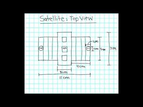
Educational video: Engineering Drawing Tutorial – NASA’s BEST Students
This educational introduction explains how drawings communicate geometry. It supports the specification and supplier-handoff discussion; it is not a glass-processing instruction or a calibrated inspection method.
Watch Engineering Drawing Tutorial – NASA’s BEST Students from NASA BEST Students


